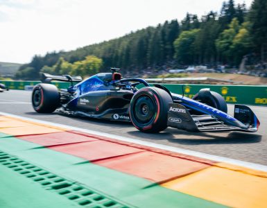
In the modern-day Formula One car, there is far more to the steering wheel to merely pointing the car where it needs to be on the circuit.
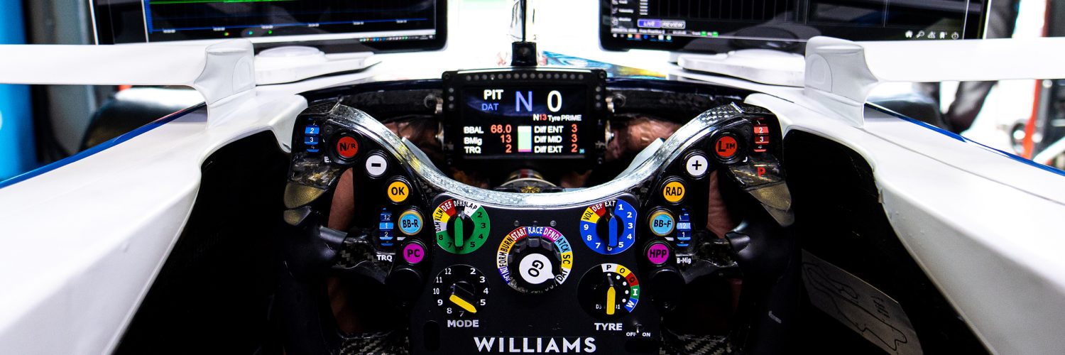
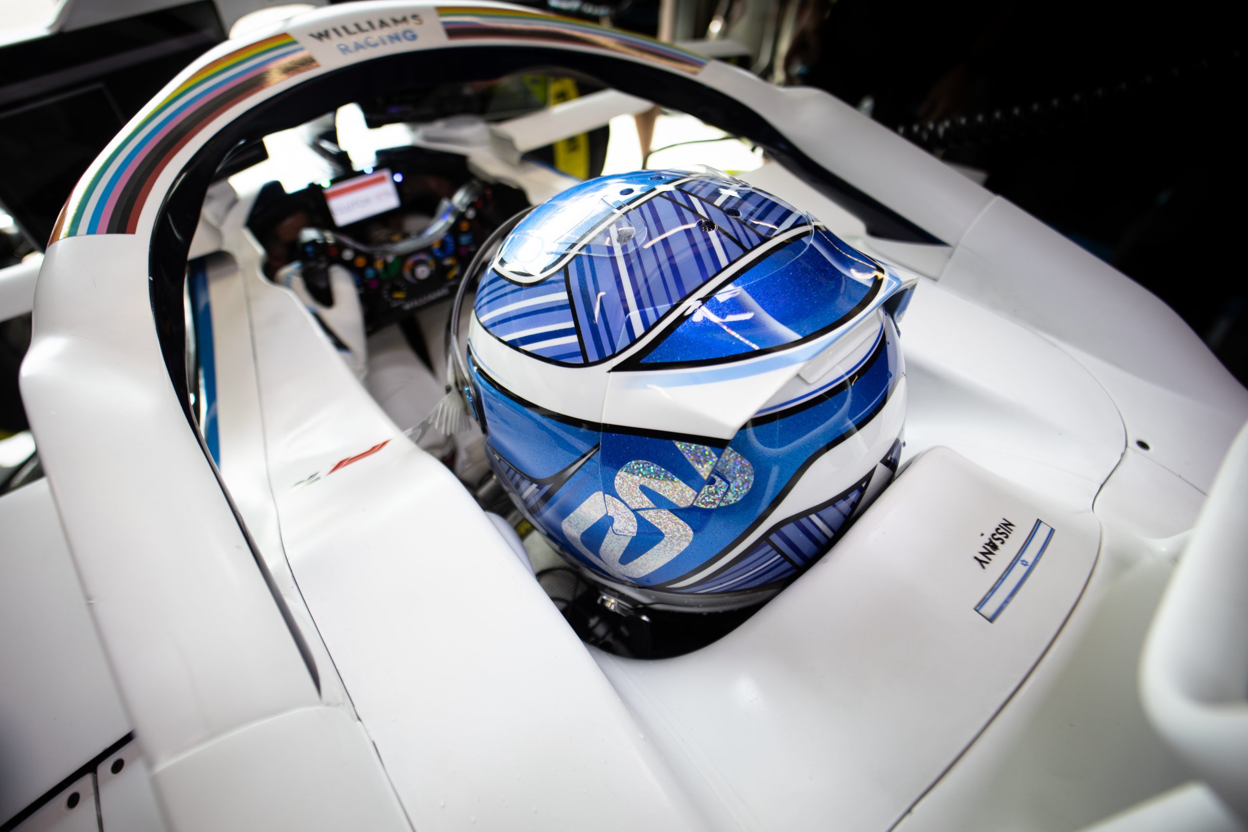
As tailored to the driver as their race suit or custom moulded seat, the F1 steering wheel allows the driver to monitor and/or control nearly every aspect of the race car. As reported last year, Robert Kubica needed a very unique system to allow him to drive the car with the limitations of his damaged right arm. With the current Williams F1 steering wheel shown recently on the team’s twitter feed, the huge range of buttons can be seen. But what are they and how does the driver benefit from them?
Although unique to each team and tailored to each driver, there is a limit on what is allowed on the steering wheel. As both the dash display and the internal control unit are specified by the FIA for all teams. This gives the teams the same McLaren Applied Technology PCU-8D display unit, with its 4.3” colour LCD display and the interface unit that links all the buttons, rotary switches and paddles back to the ECU. For Williams, uniquely, this LCD display is fixed and separate from the wheel, as is the case with all other current teams.
As the car’s ECU is also a standardised part also from McLaren Applied Technologies, there is a limit on the steering wheel to 20 buttons, 9 rotary switches and six paddles. How the team then decides how each switch works is up to them, in conjunction with the driver.
PRIMARY CONTROLS
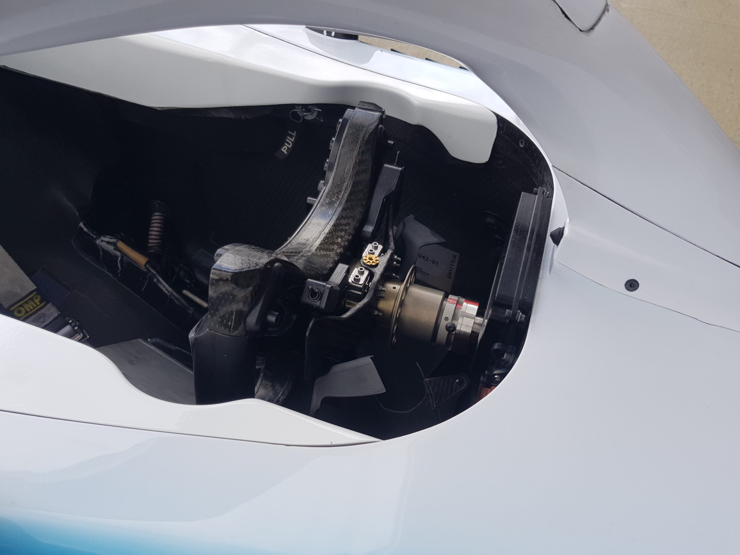
As the modern steering wheel is anything but round, the driver’s hand tends to stay on the silicone grips and will generally not move much from that position. Thus, the majority of the controls are grouped ergonomically around the thumb and fingertips, with the lesser used Rotary multifunction switches placed on the lower face of the steering wheel, requiring the driver to remove the hand from the wheel to make small adjustments.
The more often the driver uses a control during the lap, the closer its placed to the fingertips, thus the gear paddles are right by the driver’s forefinger tip, while the clutch paddles sit slightly lower down.
Changing gear is as “simple” as flicking the paddle, but rules demand that the shift must be completed 200ms after the paddle is pulled, also that the shift cannot be initiated by the rev limiter, nor that shifts can be stacked up, to go through the gears more quickly. Thus, the driver must still pull the paddle at the precise moment that maximises use of the engine power, too early and the shift will happen anyway due the time limit slowing the acceleration, too late and the rev limiter kicks in and again slows acceleration.
To aid the driver in shifting gear at the right moment, the Dash unit has a row of LEDS, that can be configured to light up in green or yellow to show the increasing engine revs and then red as the RPM nears the engine’s red line. There is also an audible system, that sounds a tone in the driver headset inside their helmet to denote the shift point. This system is also used for lift & coast during the fuel saving phases of a race. It is often heard from the driver’s race engineer to lift or shift “on the tones”.
Williams sport a pair of mirrored clutch paddles, which gives the driver the option to pull either paddle to keep the engine running during a spin, but rules demand they only use one paddle for the start of the race.
As well as the large gear and clutch paddles, Williams have smaller secondary paddles on the back of the steering wheel. Their function is not labelled, but these may be DRS activation or Overtake controls, which are not evident on the front of the steering wheel. The overtake option now gives the driver full ERS deployment, previously this would also switch the combustion engine mode to full power, but new rules this season limit the driver to the same engine mode for qualifying and throughout the race.
 BASIC CONTROLS
After steering, shifting and clutch control, the driver then reverts to the array of buttons to engage functions for communication and car control. Primary of which is the radio button, where push-to-talk system is frequently heard during broadcasts, with lot of structured talk to pass information between the driver and the pits. Other communication is made twixt driver and pits that either doesn’t need verbal prompts or teams would prefer to remain secret. Both the OK and the pit conform buttons are used for this. If given a request from their race engineer, the driver can press the “OK” button, rather than talking. The button being operated on the steering wheel is seen by the pits on the cars real time telemetry system, this is taken as confirmation the driver heard the request.
Likewise, a “pit confirm” button allows the driver to affirm a pitstop request, thus being able to be done silently from unheard on the TV radio broadcasts. It’s separate from the “OK” button, to be sure the confirmation is specifically for the pitstop and not another request requiring the “OK” button. Although there’s a lot of tyre talk, sometimes misinformation, on the radio between driver and engineer.
There is another clever system where the driver uses the “Tyre” rotary switch to inform the race engineer of the tyre’s condition. This switch not only sets the current the type into the ECU (prime, option, qualifier, intermediate and wet), but can have added positions that allow the driver describe the current phase of the tyre’s life, from good to worn out. Using this set up again means no radio broadcast is used to communicate key tactical information.
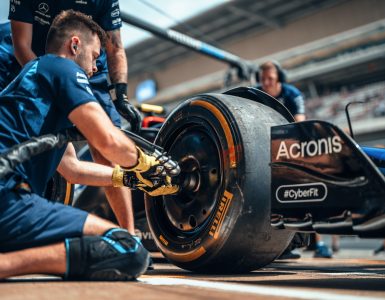
Once entering the pits, the Pit Limiter control caps the car’s speed at the prevailing pit lane speed limit, as the driver brakes on entry to the pit lane. There may also be a dashboard display to show the car is still above the pit lane speed limit, to ensure the driver brakes enough and doesn’t cross the pit lane entry limit at too high a speed. If all goes well, a near two-second pitstop see the driver keep the car in gear, with just the clutch pulled in. At other times, when returning to the pits during non-race sessions, the neutral button will take the gearbox out of gear.
Unusually, Williams split the button for neutral with the request for reverse gear. There needing to be a compound function to selecting reverse gear, perhaps a specific button, paddle or brake pedal needing to be used simultaneously to engage reverse gear. All F1 cars are required to have a functioning reverse gear for obvious safety reasons. This is still done by a gear pairing within the gearbox, engaged with hydraulics.
Theoretically, the car’s hybrid system could use the 160hp MGUK electric motor to reverse the car, but the motor is geared to the front of the crankshaft, this would require the engine to be stopped and in first gear, to actually manoeuvre the car backwards, cranking over the engine in the process. Thus, this isn’t a suitable means for reversing.
Lastly, there is a button for the driver’s drinks system, although the actual button isn’t evident on the Williams steering wheel in this picture. Around 1 litre of fluid is carried on board for the race, to replace the fluid and minerals lost through the exertion of driving the car is hotter climes.
CAR SET UP
As the car works through its fuel load and tyres in a race and with changing ambient conditions, the car’s handling will change, between understeer and oversteer, with a different balance or traction level at different corners on the track. Unable to make anything other than front wing changes at the pitstop, the ability of the team to do anything to tune the set up is limited. However, the driver does have a few tools, literally at their fingertips.
First off is brake bias. Before the current post-2014 hybrid cars with their rear brake by wire system, brake bias used to be adjusted with a dial or lever within the cockpit. Giving the driver more front or rear braking effort, to assist in preventing lock ups from worn tyres or helping the car turn under braking. With the brake by wire set up, these adjustments can now be altered from the steering wheel, the driver no longer needing to take a hand take off the wheel to make an adjustment. A simple pair of buttons (BB-R BB-F) close the driver’s thumbs allow a fine shift in brake bias forwards or rearwards, there will also be a position on the chassis rotary switch to adjust the static split of brake, as the starting point for the finer adjustments.
There is also now the option to alter the brake migration, which is a new adjustment in F1, as previously the migration was purely a function of the brake pedal and master cylinder geometry. Brake Migration is the shift in braking effort from front to rear through the braking phase. At high speed with lots of downforce and stable weight distribution, the braking is split more equally front to rear.
As the braking phase continues, the car slows; weight shifts forwards and downforce can be lost from the rear of the car as the rear ride height increases. Now more front braking can be exploited and less rear braking is required, so the balance can migrate forwards. The driver can use this setting to alter the balance of the car through the braking phase, another useful means to tune the handling of the car.
One system that is allowed to have some electronic control is the differential, this cannot be active control, only what is possible from a mechanical differential. But as with the brake migration this has become a tuning a parameter for the car’s handling. The differential can be set up to operate anywhere between open or locked during three different phases of cornering. So, there are differential settings for corner entry, mid corner and corner exit. On corner entry a more open differential allows the car to turn in more easily, as both rear wheels can rotate at different speeds.
Conversely a tighter differential setting induces some understeer, as the rear wheels try to remain at the same speed as each other. You can immediately see that this ENTRY setting becomes useful in controlling understeer and oversteer. Likewise, on corner exit, with the car having differing traction and power oversteer traits, the EXIT setting is useful too. Thus, the driver has both the entry and exit settings available on the top rotary switch at their thumb tips. The MID setting isn’t as influential, so this does not require a dedicated switch and is set up from the chassis rotary switch on the face of the wheel.
To control the cars balance on corner entry from the brakes and differential is clearly a beneficial adjustment, there is another means to balance the car from the steering wheel – engine braking. How much drag the engine places on the rear wheels when lifting the throttle pedal will affect turn-in, as with the differential controls bringing understeer or oversteer.
Engine braking is crucial and there are points on the track that the driver lifts but not brakes, so the balance comes from how much the engine retards the rear wheels. In a similar, but more subtle way to a hand brake turn! The engine braking set up would be from one of the multifunction rotary switches, as it isn’t a frequently altered parameter.
POWER UNIT/CHASSIS MANAGEMENT
Given the complexity of the current Power Units (PUs) it isn’t a surprise that a lot of the pit to driver radio talk is centred around PU management. Some of this is simply having the PU in the right mode. The Mercedes HPP supplied power unit in the Williams comes with various modes and settings, with three rotary switches dedicated to the Power Unit control, from the ERS torque (TRQ) rotary on the lefthand wheel spoke, the PU MODE and central GO rotaries all allow the driver to manage the huge range of PU management functions.
Just looking at the GO rotary switch, there are specific settings for; in Laps, grid formation, burn outs, race starts, race modes, defend, attack and safety car. All these group various settings into one switch position to maximise PU performance, fuel economy and life. There are then sub menus and settings that the driver can delve into, from the switch, this may be to turn off faulty sensors or functions, or to alter base settings for PU parameters. The specific switch position and code are rear out to the driver from the race engineer over the radio, the driver then turning the switch to the relevant position and entering the code number via the “+” & “-“ buttons on the wheel. This maintenance can be crucial in keeping the car going through a race, despite problems or failures within the PU.
Chassis problems with the hydraulics and gearbox are also solved in a similar way with their own rotary switches. These switches can also provide simple adjustments for the driver, such as the dash backlight level or the radio volume!
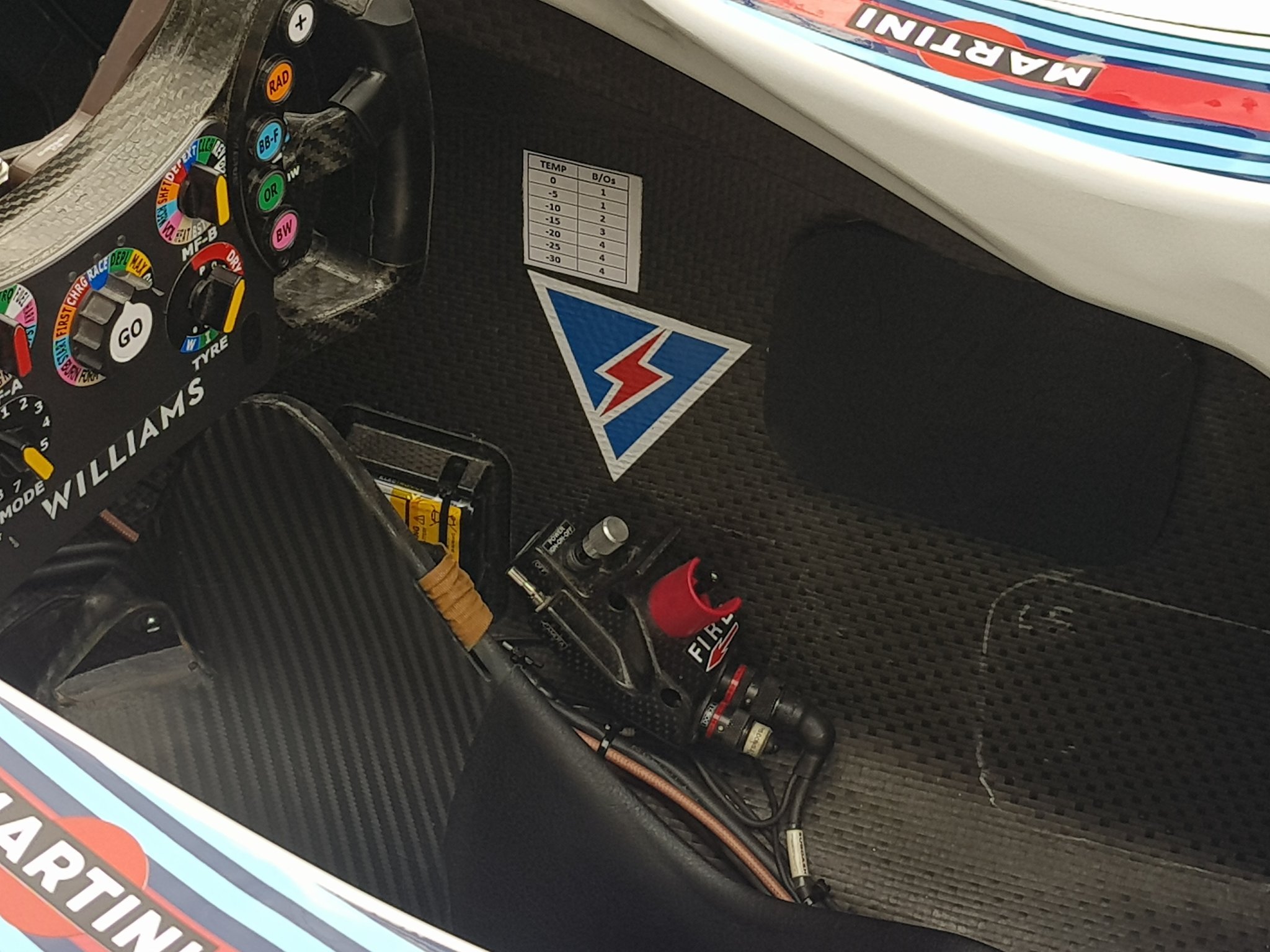
OFF THE WHEEL
Other than those switches on the steering wheel, the F1 cockpit is sparse and only has buttons in one other place, the master switch panel. For Williams this is on the right hand side of the cockpit, low down alongside the drivers’ leg. The panel contains the electrical master switch and the extinguisher button.
The master switch is like the ignition key for an F1 car, albeit there’s no actual key! The switch is a robust three position set up, with a sprung toggle to prevent accidental use. In position “0ff” all of the car’s electrics are off, in position “On 1” the basic 12v electrical systems are on, so the ECU and dash are powered up, then in position “On 2” the fuel and ignition systems are powered up and the car can be started. Knocking the switch from position “2” to “1” kills the engine. Some teams can use the hybrid system to restart the engine should it be stopped or stalled, a sequence of switches between the three Master switch positions informs the ECU to spin the MGUK and start the engine. However, The Mercedes PU is not set up for self-starting, so Williams do not have this function.
The extinguisher button is self-explanatory and used by the driver in the event of a fire to discharge the extinguishant into the cockpit and engine bay.
Teams vary the design and placement of the master switch, so to aid the race marshals finding the right switch in an emergency, a booklet detailing the switch location and function for every car is produced and circulated at each race.
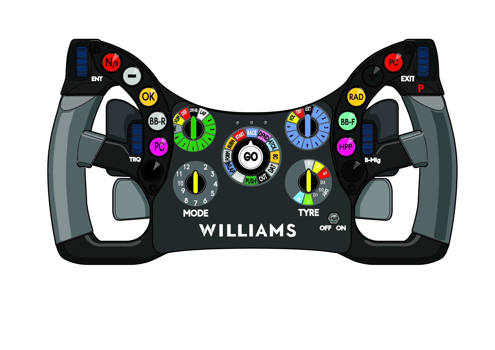
DETAIL BREAKDOWN
Buttons
N R – Neutral and Reverse gear selection
– Minus decreases value from multifunction menus
OK – Acknowledge communication from pit radio
BB R – Brake Bias adjustment towards the rear
PC – Pit Confirm, acknowledges to pit next lap
LIM – Pit lane speed Limiter engaged
+ Plus increases value from multifunction menu
RAD – Push to talk on radio
BB F – Brake Bias adjustment towards the front
HPP – Mercedes AMG power unit menu
Rotaries
ENTRY – Adjusts differential for corner entry
TRQ – Power Unit torque setting
Multifunction – Misc chassis and electronic functions
MODE – Power Unit mode
GO – Powertrain and Electronics modes
TYRE – Tyre type and wear phase
Multifunction – Misc chassis and electronic functions
B Mig – adjusts how the front to rear brake bias changes while braking
EXIT – Adjusts differential for corner exit