Ask any junior formulae driver who gets to test an F1 car for the first time what the most impressive thing is, and most of the time they will say it’s the brakes. Considering the F1 car’s near 1000hp and +4g cornering performance, it’s the +5g braking performance that gets all the attention. Achieving this incredible feat, stopping the car from 200mph in just a seconds, is a complex mix of downforce, mechanics, and electronics.

Performance
A current F1 car’s braking system is made up of the brake discs, calipers, pedal and master cylinder – all linked by pipework and with a brake-by-wire unit controlling the rear brakes. Despite the deceleration available, the brakes are heavily regulated to limit their ability to deliver even greater performance.
Slowing the car from 210mph approaching the 13th turn around the Montreal’s Circuit Gilles Villeneuve, the driver will brake for just 2.09 seconds slowing to 83mph in a mere 122 meters, which is about 20 car lengths! In order to achieve this amazing feat, more is required than just the brakes, it needs the wide Pirelli slick tyres for the traction, plus huge amounts of downforce and powerful leg muscles.
It’s only possible to get this 5G performance because the car has so much grip at the tyre contact patch. To make the best of the braking potential available, most effort is required at the start of the braking event, when downforce is the highest. The braking effort from the driver is not quite on/off, as they will need to ease back on the pedal as the downforce decreases with speed, in order to balance the retardation with the grip available.
This blend of downforce, tyres and braking system makes F1 cars the most efficient decelerating race machines in motorsport.
Discs, calipers
Everything depends on the bite of the brakes on the discs, so F1 cars run carbon discs and pads with aluminium six pot calipers. Carbon fibre is used for two main reasons and it’s not the myth about steel brakes being less powerful. Fundamentally, carbon fibre is lighter than a steel disc, but it also copes with running at high temperature better than steel. Having first appeared on aircraft, with the technology being introduced to F1 by Gordon Murray at Brabham in the early eighties, the compromise with carbon discs is the cost. Anything lighter on an F1 car is worth the cost, so carbon disc brakes have been the de facto choice since the early teething problems were worked out in the eighties.
Over this time, the disc and pad pairing has been rapidly developed. They are both made from the same friction material and thus both wear out at similar rates. Maintaining a working temperature has been the challenge with these brakes – too cool (<300c) and the brakes don’t bite as hard, too hot (>1000c) then the material oxidizes and wear increases. Keeping heat in the brakes is achieved with the careful sizing of the brake ducts, and this is less of a problem. However, overheating is a much greater issue. If the brakes are run white hot for too long, the oxidisation will wear the disc too thin and the disc can fail catastrophically. Initially, radial cooling holes similar to steel discs were run. As teams were able to exploit the brake materials even more, they needed more cooling, so the number of cooling holes increased commensurately. From 100 in 2005 to some 1500 in 2019, the cooling holes are at the point where any more would structurally weaken the disc too much. This limitation is based on the rules that the disc must only be 32mm thick and capped at 278mm. These rules work to prevent even more powerful and expensive brakes, while also allowing them to be fitted inside the regulation sized 13” wheel rim. At this size, the brake disc weighs just 1200 grammes!
In first practice, a new pair of discs/pads will be bedded in, then removed and reused as the qualifying\race brakes. Meanwhile, a used set will be fitted for the rest of free practice which gives the parts a life of just 500 miles! Brake material is supplied to the team by two key suppliers; Brembo and Carbone Industrie.
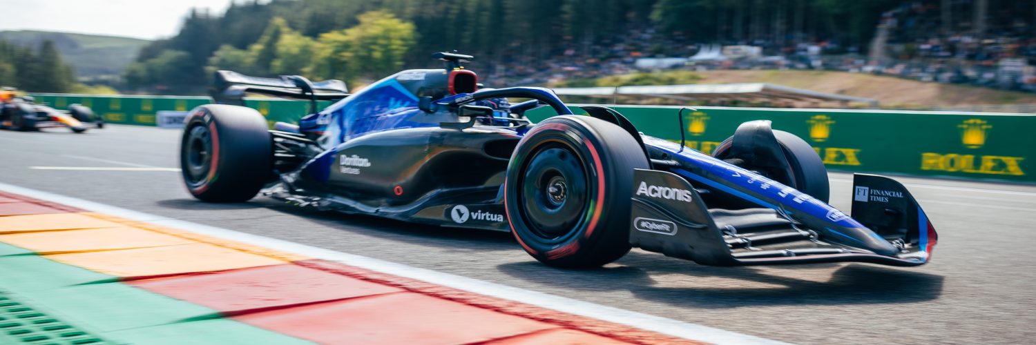
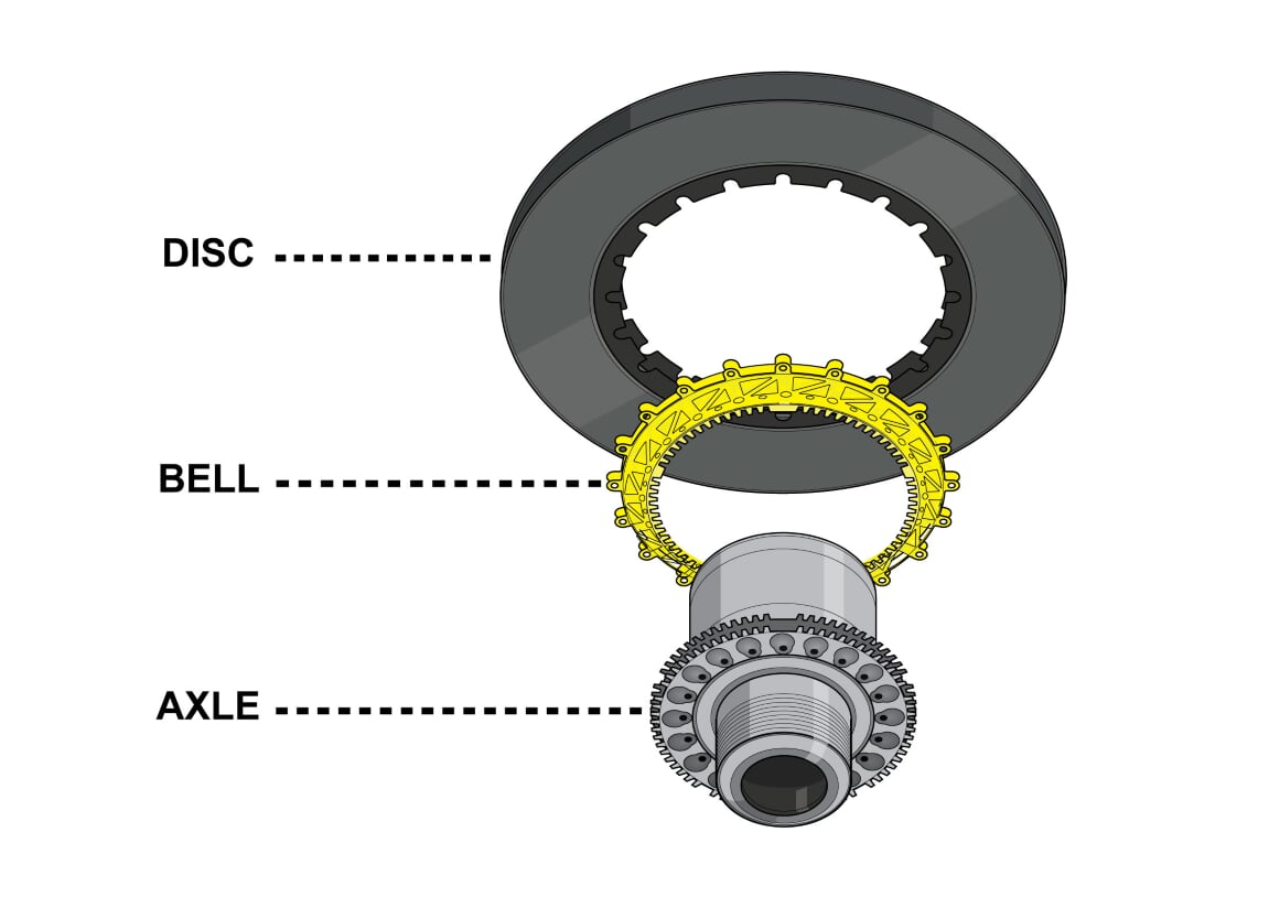
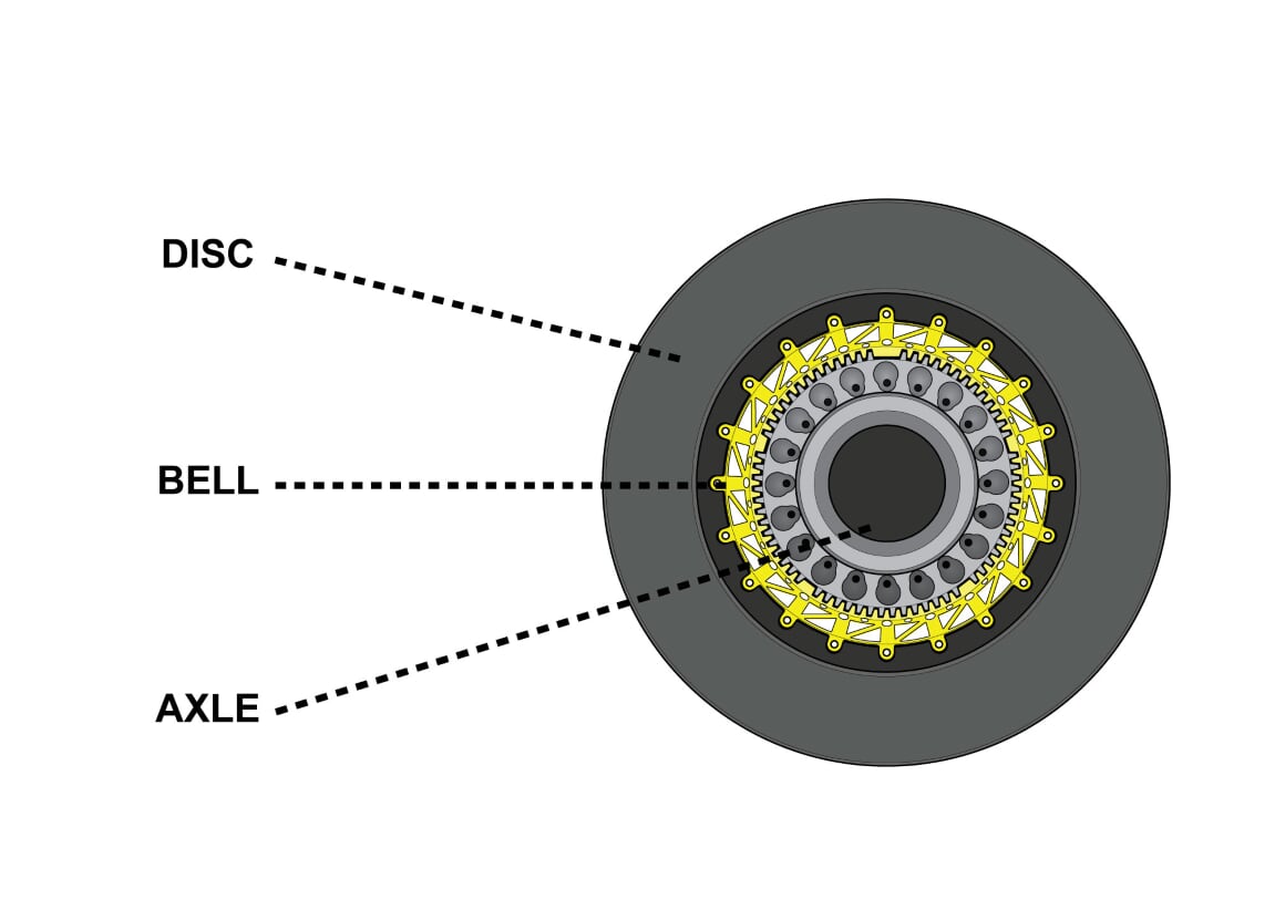
The disc mounts the axle via an intermediate ring, known as a disc bell. This is a precision-machined part that matches the inner splines on the disc and the corresponding splines on the axle. The splines do the majority of transferring the torque from disc to axle, although bolts are also used. These are limited as the hole for the bolt invites stress into the assembly. Teams may manufacture their own disc bells or the brake manufacturer may do so. Either way, the precision is crucial to prevent stress occurring which may see the disc or the bell fail.
Cooling for the disc is routed around the upright in carbon fibre ducting and into the cooling hole son the inside of the disc. Every team has their own method of achieving this, either ducting direct to the disc or routing air through channels in the disc bell then into the disc.
Gripping the disc is the caliper, again a heavily regulated part, to limit its potential performance. Current F1 calipers are limited to one per corner, six pistons, two mountings and made from aluminium based alloys.
Despite these limitations, iterative design sees the caliper as stiff for ever decreasing weights, the use of Finite Element Analysis (FEA) software packages being critical to the caliper body design. Equally, the thermal stress on the caliper is researched with simulation tools. Heat builds up in the caliper body as the disc runs through the central channel, making the caliper hottest near the last of the opposing piston pairs.
Luckily, the need to cool and lighten the caliper sees the body skeletonised, with drillings and openings around the piston bores to save weight and reject heat. Even the pistons have a ring of radial drillings to cool the piston and brake fluid behind it from the heat of the carbon friction material at work. Likewise, the carbon brake pads can have drillings to try to insulate the caliper from the heat.
Made from aluminium lithium alloy, or other aluminium alloys with a stiffness limit of 80Gpa, the caliper body is machined from solid. Brembo is currently the dominant manufacturer and AP racing are also a common supplier, while 920e supply Racing Point and Akebono supply McLaren.
Although six piston calipers are demanded by the rules, teams can run smaller numbers of pistons. Since the 2014 rules exploited more braking from the ERS-K, the rear brakes are hardly required at some circuits, only when initial braking is high is the caliper used to brake – the rest of the braking effort coming from the regenerative braking effect. So, teams can run four piston rear calipers to save some weight, and balance the effort and cooling required from them.
Pedal
If the sharp end of the braking system is the discs and calipers, then the action all stems from the humble brake pedal. F1 brakes can no longer have any power assistance, so the brake line pressure must all be generated by the driver pressing on the pedal to operate the master cylinders. What’s more, the driver brakes with solely their left foot, which needs to exert some 125kg on the pedal for the maximum braking effort. It’s hard to exert such a high load with any deftness with muscle alone, but luckily for the driver, the G-forces from the braking also act on the left leg, adding to the muscle’s effort to apply the 125kg pressure.
Typically, the pedal is now made from carbon fibre to the team’s own design. It’s a strong safety critical part, yet still weighs very little. The footplate is adapted to suit the driver’s preference to hold the foot in position over bumps and through corners. Additionally, to suit different drivers, the leverage ratio between pedal and master cylinders can be achieved with different pedal designs.
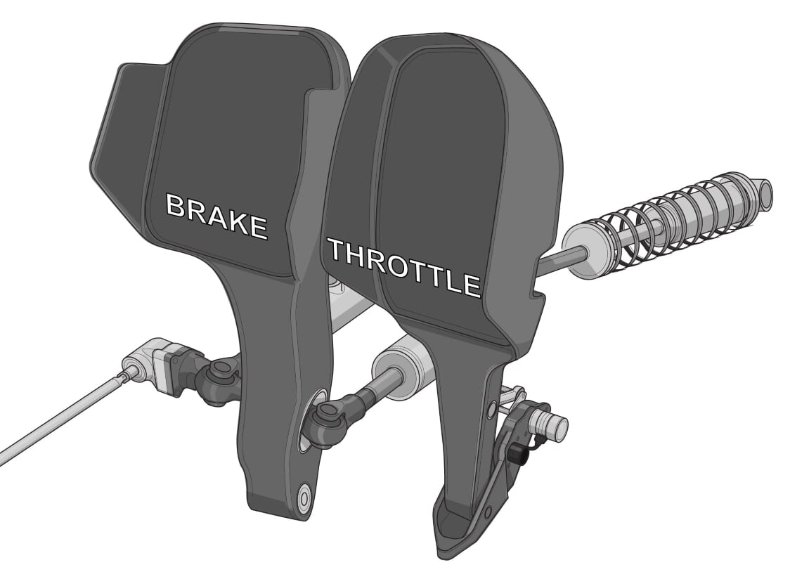
Currently, the pedal operates two master cylinders. These create the pressure in the fluid line to the front and rear brakes, and each master cylinder provides a separate supply of brake fluid from separate reservoirs mounted in the nose. This split system dates back to the days when brakes failed more regularly – still a safety factor nowadays. Should there be a brake failure, the car will be almost controllable with just the front or rear brakes working.
The master cylinders themselves are microcosm of F1 complexity. Still fundamentally just a piston compressing fluid within a cylinder to create pressure, the contemporary master cylinder is a two stage device. There is a stepped piston, the initial stroke compresses the first piston to create a sudden large pressure increase, this rapidly moves the pads back into contact with the disc and then applies pressure for maximum initial braking. Then the second piston is used to maintain that pressure for the duration of the braking event. Master cylinders tend to be supplied by the caliper supplier, although that isn’t necessarily always the case.
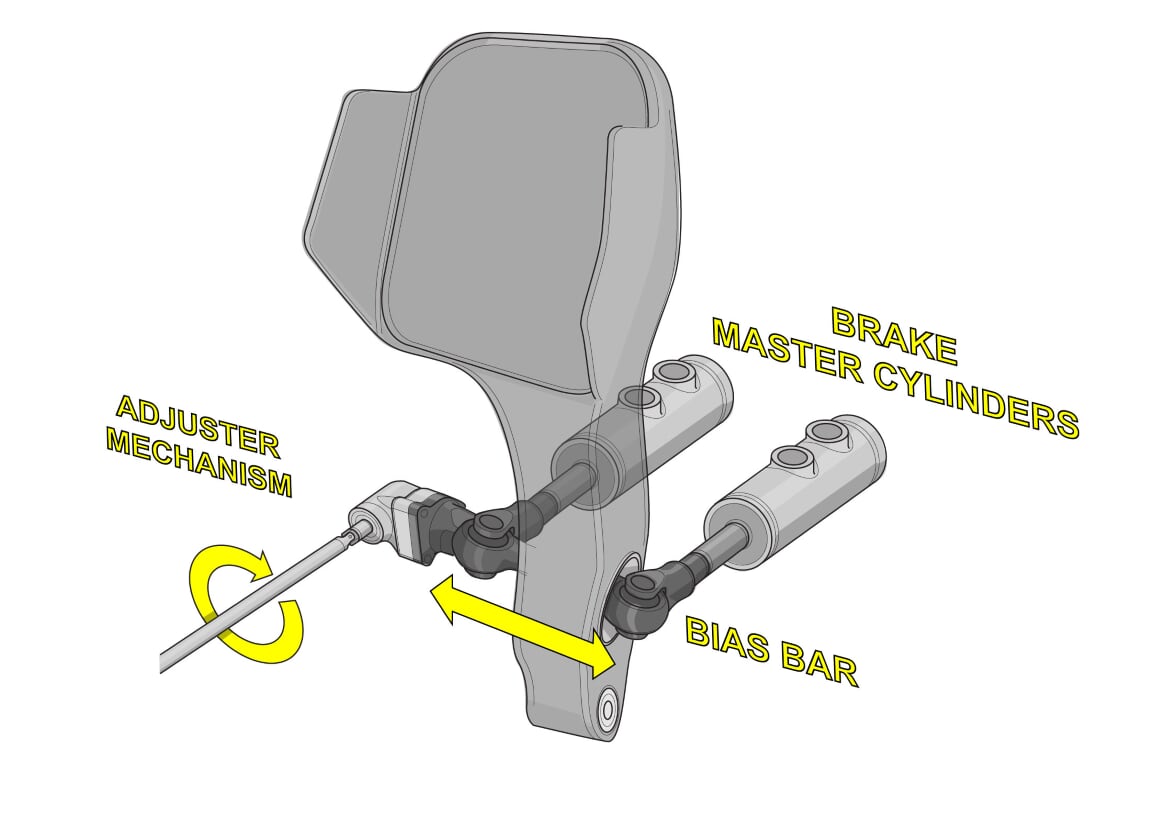
As there are two master cylinders, one each for front and rear brakes, there needs to be a means to balance the pressure between them to match the car’s weight distribution and grip. The master cylinders may have different bore sizes, but there’s also the adjustable bias bar mechanism. One end of each master cylinder attaches to a pivoting beam known as a bias bar. The pivot is aligned with the pedal, and if the master cylinders are equidistant along the bias bar, there’s a 50%-50% split in effort between them. If the driver adjusts the bar to have one master cylinder offset more than the other, the front to rear bias can be varied. This adjustment can be achieved with a rotating adjuster or a more complex adjuster with pre-sets. This is what we used to see the driver adjusting with their hand around the lap. The bias bar still exists, but the bias is now more easily achieved with the brake-by-wire system via steering wheel buttons.
Another effect with the brake bias is not just the static split of front to rear braking, but also how the bias changes through the braking event. As the rear of the car will get lighter from weight transfer during a long braking episode, the bias ideally needs to shift with it. This used to be achieved with the pedal and bias bar geometry, but again is now much easier to adapt via the Brake-by-Wire system.
Brake fluid is transferred under pressure through pipework from the master cylinders leading to each caliper through the wishbone legs. Wherever there is movement required, flexible braided pipes are used. Elsewhere, rigid pipes are used to maintain pressure within the system.
Brake-by-Wire (BBW)
Since 2014, with the change in the energy recovery systems (ERS), the use of a Brake-by-Wire (BBW) system has been allowed for the rear brakes. As the ERS-K recovers energy under braking, the drag of the MGU acts as a brake, also slowing the car. However, this effect isn’t constant, the braking effort from the MGU-K will vary depending on its Regen setting and how charged the battery is.
With this change in ERS braking effort, the driver will suffer imbalanced braking, sometimes getting rear braking from ERS, sometimes not and not always with any warning. So, the FIA allow a system termed BBW to control the rear brakes. There is still a rear master cylinder at the pedal, but the brake line terminates at the BBW unit mounted inside the gearbox. This unit recognises the braking demand by the driver, and based on the pressure in the rear brake line, it will then know whatever regenerative braking effort the ERS will apply via a signal from the SECU. It then deducts one from the other and via a hydraulically operated active master cylinder it will apply only the pressure at the rear brakes needed to off the ERS effect, giving the driver a balanced braking event. That’s the simple explanation! The actual software to give a consistent braking effort to the driver is far more complex. Moreover, the driver will get a different feel at the pedal, as the rear master cylinder is effectively capped off, so some compliance is put into the system with valves and accumulators to replicate the conventional pedal ‘feel’. Being safety critical, the BBW unit has a failsafe. Should the sensors or active master cylinder fail, the brakes return to being operated by the pressure in the rear brake line. Also, to prevent any pseudo anti-lock brake software being used, wheel speed cannot be a factor in the system.
Now, with electronic brake bias possible, the drivers use controls on the steering wheel to alter brake bias and brake bias migration, never needing to take a hand off the steering wheel to adjust them.
So, the next time you see a driver braking into a corner from 200mph to close to a standstill, it’s worth contemplating just how much is going on when the driver stamps on the pedal.
Brilliant detail. Outstanding breakdown of the system as well. Top marks.