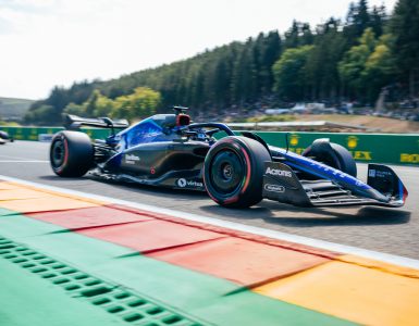
As the FIA’s pioneering electric single-seater series, Formula E is now moving into its seventh season. Along the category’s short history, it has gone from a full spec series to a manufacturer-lead bespoke powertrain formula. It survived 2020’s Covid-19 outbreak with a pragmatic series of cost-cutting measures and a unique one-venue season finale. With the sport’s future direction now very much back in focus, the lessons of recent years are keeping the rules aimed at cost reduction and closing loopholes to keep the series as competitive as ever.
HOW IT ALL STARTED
Formula E started in 2014, with teams competing a season with battery-electric race cars. All of which were of the same hardware specification, that is both Spark Racing Technology chassis, Williams Advanced Engineering Battery and McLaren Advanced Technology supplied powertrain, only the software being open to development.
As the season started mid-year and ran into the next calendar year, the championships are described sequentially, rather than by the year, so the 2015/2016 season was called Season2. This second season allowed a set of nominated manufacturers to supply the powertrain, with the chassis and battery remaining the same spec parts. Seasons 3 and 4 opened up the powertrain to greater power outputs and energy recovery rates. With the battery capacity available from the First Generation (Gen1) specification, the 45-minute races required a car swap mid-race. The driver pitting and jumping from one car to another, was itself as much a spectacle as a mid-race fuel or tyre stop, but still a negative image for the category trying to promote electric vehicles.
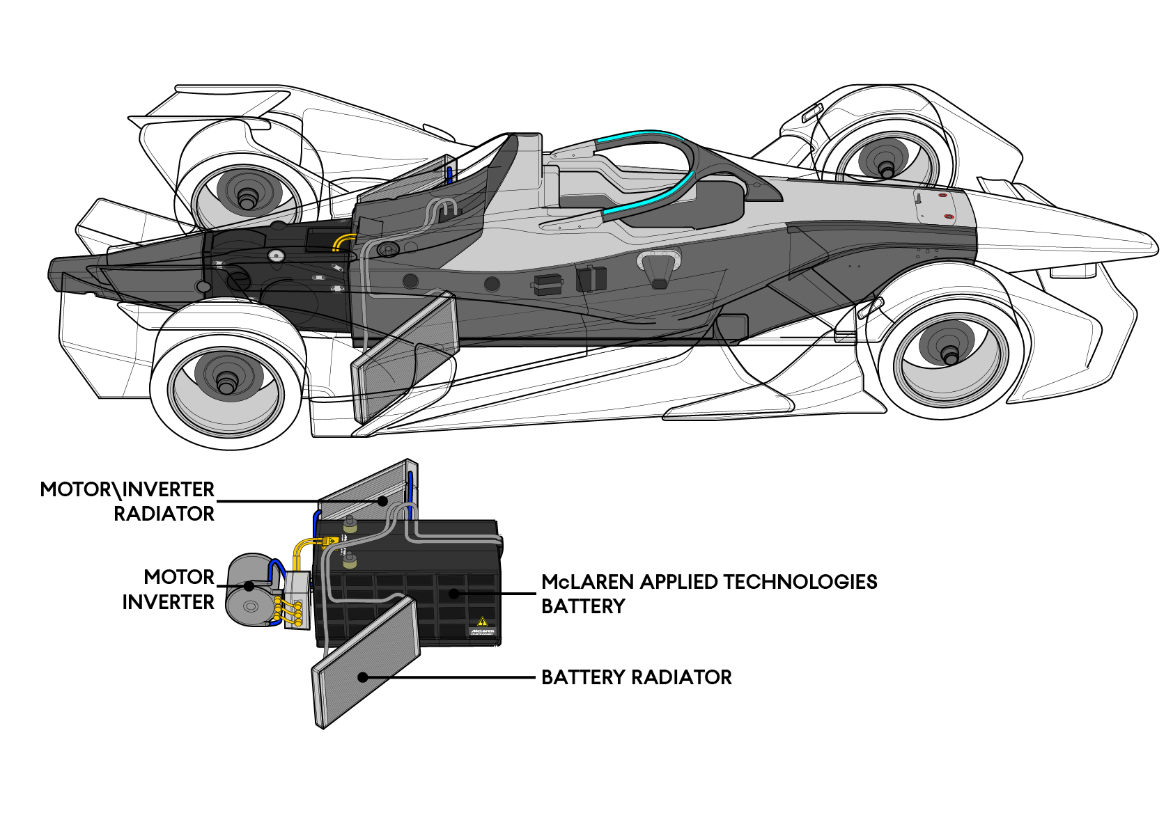
Then for Season5 there was a new chassis from the same partner, albeit coupled with an all-new Battery from McLaren Applied Technology. With its ‘batmobile’ styling, the Gen2 car gained a battery with twice the energy capacity, making car swaps a thing of the past.
Not without its critics, Formula E has become an attractive and cost-effective category for car manufacturers to showcase their EV technology, with manufacturers; Audi, Porsche, BMW, Mercedes, Jaguar, Nissan, DS automobile, Mahindra and NIO making up the majority of the 12 entrants. With the big names comes big investment and the stakes are getting higher with every season, each team wanting to win races and ultimately the championship.
As a result, the level of engineering applied to the powertrain has grown immeasurably, truly F1 levels of engineering and preparation are apparent, but with this comes the pushing of the rules to the limit and none of this comes without an economic hit. This pressure has been evident since Season 5, albeit the whole formula came together as one to work out the best route through the COVID-19 crisis in Season6. Looking ahead for Season7, the rules package has aimed to level the playing field, by limiting the running costs and closing technical avenues for exploitation.
HOW IT’S GOING
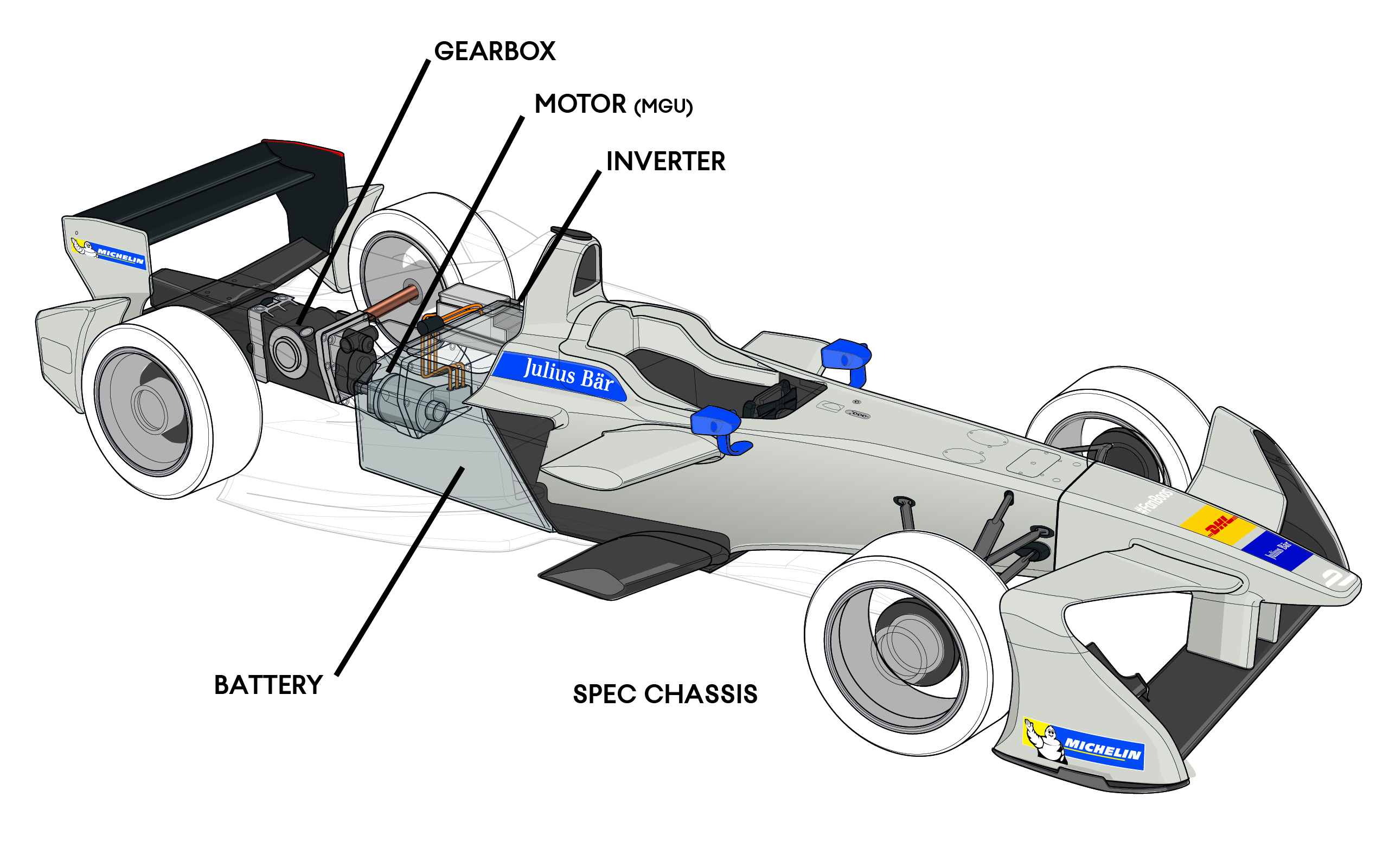
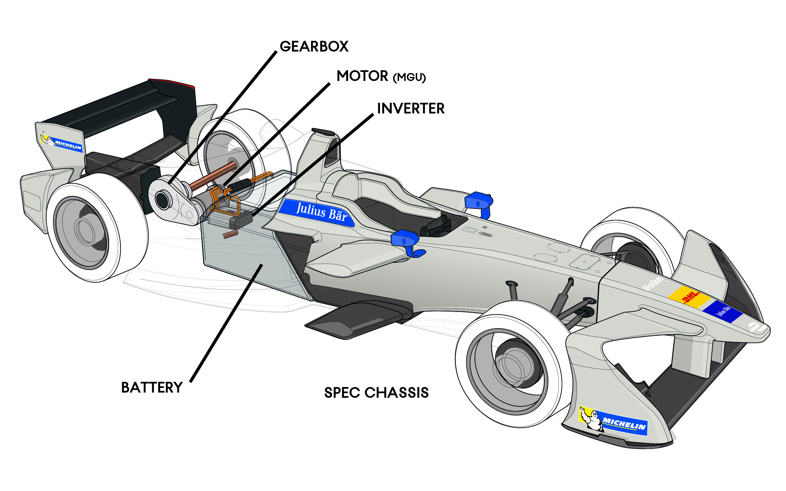
For Season7, Formula E will continue to run the unchanged Gen2 chassis, the planned EVO update to the bodywork being held back to manage costs. French EV race car specialist Spark Racing Technology continues to develop the chassis in partnership with the Italian race car manufacturer Dallara. The Gen2 car was a progression from the Gen1 not just in its looks, but the car’s layout changed with the shift in Battery suppliers. Whereas the Gen1 car mounted its Williams developed battery as a structural element between a truncated monocoque and the powertrain, now the Gen2 car has a more conventional monocoque, where the McLaren supplied battery sits inside the area behind the driver, its location more akin to the petrol fuel tank positioned in any other single-seater.
With the spec chassis and battery, Formula E lists eleven companies allowed to develop powertrains for the teams in the series. With twelve teams it’s clear that it’s still possible to enter as a customer team and buy the entire powertrain from a homologated manufacturer.
Other than changes to aero and suspension set up, the teams cannot change or develop any part of the chassis outside the regulated powertrain envelope. Thus, the freedom for hardware development is limited to; Motor, Inverter, DCDC, VCU, Final Drive, Rear suspension (excluding rear uprights), driveshafts, powertrain cooling package, wiring loom and the rear subframe (between the monocoque and rear impact structure). Numerous technical regulation control what manufacturers can do with each of these elements, the entire powertrain package weighs in at under 125kg.
BATTERY
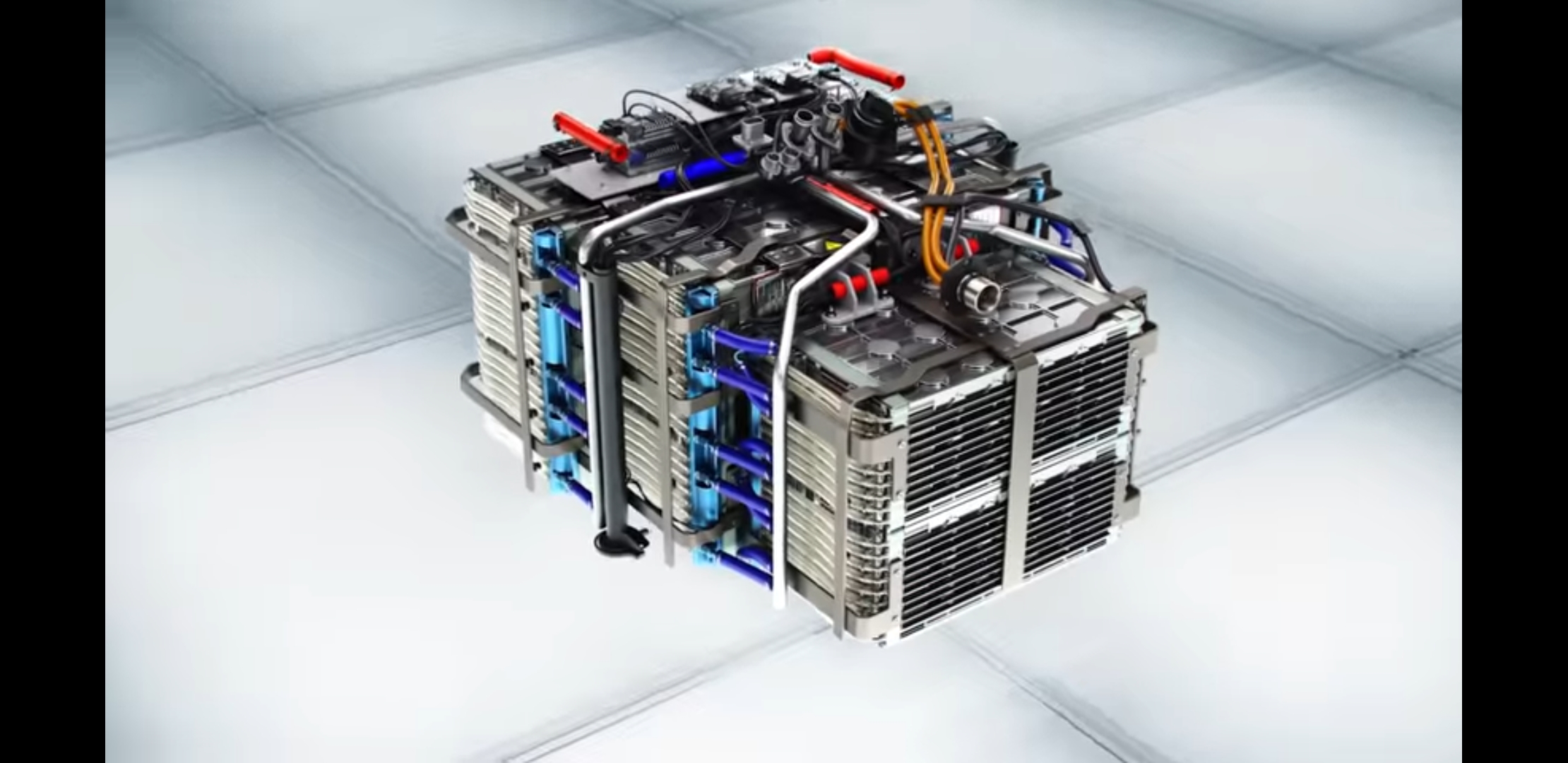
Known within Formula E as the RESS, (Rechargeable Energy Storage System) the main battery pack is now supplied by McLaren Applied Technology, with a large part of the development partnered with Atieva, the California EV manufacturer better known under the Lucid brand banner. This battery supplies the energy to power the cars electric motor, rated at 54kwh, nearly double the Gen1 car’s battery capacity. Running at 880v the battery is formed from +5000 cells Li-Ion supplied by Murata (nee Sony), despite the huge potential of the battery, these cells are in fact tiny AA sized cells, more recognisable as being fitted inside a vape or TV remote control! Even the technology of the cells is not especially revolutionary or new, in fact they predate the 2018 debut in Season5. It is how they are packaged, cooled and deployed, within the five main modules and sub modules inside the unit’s carbon fibre casing.
Management of the cells is achieved with a Battery Management System (BMS) inside the battery case, which monitors the voltage, charge and temperature of every cell. Then the BMS software manages the charge/discharge cycles of the entire package for maximum performance through a race and season (1 battery per car per season). Also, the BMS monitors the battery’s safety, cell temperature can rise and if left unattended can explode and catch fire.
With the rapid deployment and harvesting of energy around the lap, the cycling of electricity through the battery creates an immense amount of heat. While the thousands of cells operate best inside a temperature window of around 30°c, too cool (25°c) and they become less efficient and too hot (35°c) and they present a great risk to the safety of the event. It’s not just the body of the battery that will heat up, but also the positive/negative contacts get extremely hot. So, the design of the heat exchanger plates inside each battery module need to conduct heat away from these two areas very effectively. These cooling plates are formed of both a flat plate against which the contacts will be placed against, but also a zig-zag of further plates resting a single cell in between each “V” to cool its cylindrical body.
By regulation, the cells are cooled by an oil-based fluid inside the heat exchanger plates. There’s an electric Bosch pump circulating the fluid around the cells and out to an oil cooler in the right-hand sidepod. Should a cell overheat, the BMS will derate the battery to cap its output and even shut down completely if temperatures reach a critical level.
Another safety factor is the battery being safe from vibration, shocks and crashes. Being inside the monocoque already provides a level of protection, but the case has a semi structural casing with layers of Xylon, carbon fibre and electrically insulating material. This protects the vulnerable cells, even in the event of a 50g impact.
MOTOR
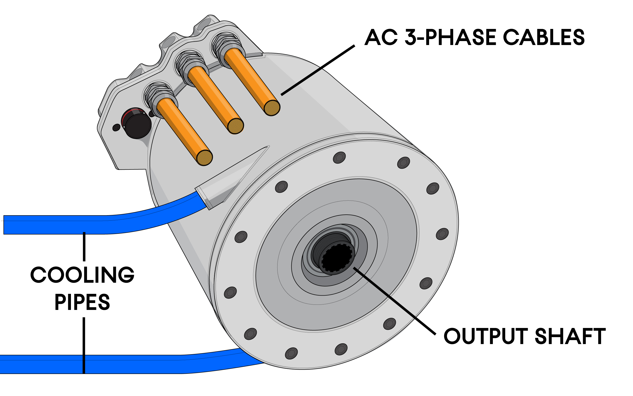
As much the heart of the Formula E race car as the battery is the motor, in all cases this is a permanent magnet synchronous motor. Which works both as a motor to drive the car forward and a generator to recover energy under braking, thus they are often termed MGUs (Motor Generator Unit). The power output of the motor is now regulated at a maximum of 250kW, which is equivalent to 335hp. Despite the MGU being relatable to any other race car’s engine as the means of propulsion, the MGU is tiny in contrast to an equivalent 335hp combustion engine. The motor weighs just over 20kg and is about the size of an extra-large roll of kitchen paper. Being an electric device, the MGU produces is full 200kNm of torque at zero RPM with a working rev range up to 20k RPM. Given this performance, the current series of motors do not multiple gear ratios to multiply the torque of the motor, so Formula E cars run without a gearshift or clutch.
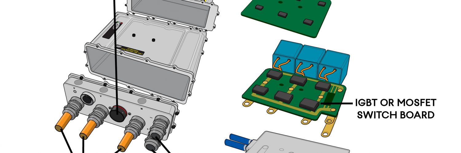
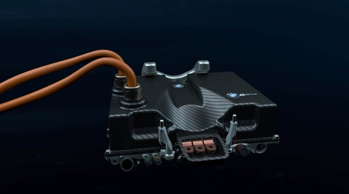
INVERTER
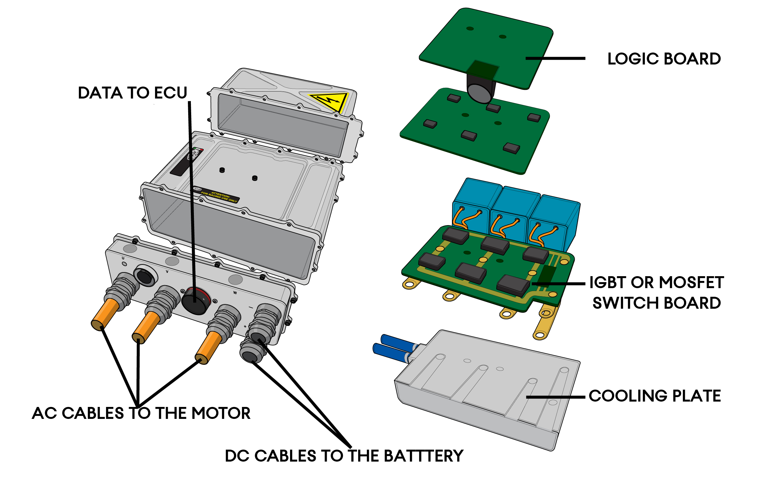
Being a three-phase electrical device, the motor requires an AC power source created from the DC battery. Basic electronics reminds us that DC to AC conversion can be done simply with four diodes, but the Formula E level of technology is well past this basic passive set up. Instead an Inverter/Rectifier is used to convert between the DC and AC depending on whether the car is accelerating or regenerating power under braking. In F1 parlance, these devices are called Control Electronics (CE), but in Formula E this is simply termed the Inverter.
Starting with the two orange cables coming from the DC battery into the Inverter, a set of semiconductor switches transform the current into three alternating waveform outputs on the other side of the unit. From the Season1 car and early manufacturer powertrains, the inverter has been developed dramatically. As the greater the voltage it can handle and quicker it switches, the more performance you gain from the Motor. Early Formula E inverters used Silicon IGBT switches, these soon struggled to perform with the increasing demands of the motor, their thermal limit capping performance. With the 880v of the Gen2 car, all manufacturers needed to switch to Silicon Carbide MOSFET switches, these cope better with the power transmission task. An added benefit they are far smaller and needed less cooling than the outgoing Silicon inverters.
As with any electrical device, the inverter gets hot. It’s typical for the team to share a cooling circuit with the motor, using a water/glycol coolant electrically pumped through a radiator in the left-hand sidepod. Performance can be gained if the radiator can be smaller, creating less aerodynamic drag and reducing weight, so the detail design of the motor/inverter can aid car performance beyond their primary tractive function.
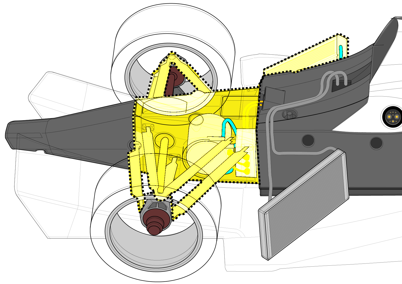
FINAL DRIVE
As explained above, the torque delivery over such a wide RPM band means that Formula E cars no longer use multiple gears. However, the 20k rpm upper rev limit means that the motor needs reduction gears – required for the motor to match wheel speed. Furthermore, rules demand the rear wheels are driven by a single passive differential, with no method of torque steer being allowed from the motor/differential package. The entire final drive geartrain is typically contained within a machined aluminium casing, enclosed with its own oil supply and pump. This ‘simple’ final drive package pioneered by Renault in Season2/3 and has been established layout since the Gen2 car was introduced. With diminishing returns from the layout, gains are now in the efficiency of the set-up, reduced friction from the gear teeth, bearings and seals, as well as parasitic losses from running the gears\diff in the gearbox oil.
REAR CASING
To support the structural function normally associated with a gearbox casing, teams use a rear casing to support the powertrain rear suspension and crash structure. Now exclusively a carbon fibre component, earlier powertrains employed aluminium castings or steel tubular spaceframes. Carbon fibre being both light and stiff, with the ease of small production runs being more effective than producing castings. The casing bolts to studs on the rear of the monocoque.
AUXILLARY SYSTEMS
Away from the mechanical and high voltage systems, the Formula E car also requires several subsystems, first amongst which is the Vehicle Control Unit (VCU). In motorsport terms, this is the ECU. But without the need to control a combustion engine and multi ratio gearbox\clutch, the ECU largely only controls chassis functions from the driver’s inputs the Vehicle prefix. McLaren Applied Technologies supply much of the grid, having done so since the spec car of Season1. Also, Bosch and Magnetti Marelli are involved with the supply of ECU’s.
With the ECU, steering wheel and dash running on a 12v power supply, the car also needs more than just the 880v from the RESS. This can be done with a DCDC converter, an electronic unit that is powered from the RESS and puts out 12v and sometimes 5v for the auxiliary system and sensors. As the car will spend a lot of time in the pit garage, requiring these systems to be running, but not the high voltage systems, there is a small 12v battery mounted in the cockpit to support these systems.
THE TRICKS OF THE TRADE
The annual challenge of Formula E is largely centred around powertrain design, although the race team operation is critical on a race by race basis. To specify the power of the car rather than size components (i.e. Combustion engine cubic capacity), Formula E are able to measure the input/output of the battery. Given this output, it is down to the teams to lose as little of that power from electrical losses and mechanical friction. The less they lose, the more power they have to play with and the further their energy allowance will take them. With round trip efficiency in the high 90%s, again there are diminishing returns with driving this efficiency, so other lap time factors are being looked at ever more closely by the teams.
On the basic packaging of the powertrain, almost all manufacturers have now gone with a transverse MGU, driving reduction ring gears to the differential. This logical layout keeps the power flow from motor to final drive gear in one orientation, reducing losses and creating a neat all-in-one package. The motor sits low inside the rear casing, leaving the inverter to either be mounted above or ahead of the motor. This creates a light package with a relatively low Centre of Gravity height.
BMW, however, have gone a uniquely different route since they became a full entrant in Season5 with the Andretti team. Their motor is mounted longitudinally in the car, driving through a bevel gear set to the final drive gear around the differential. While the losses from a bevel gear set up might appear to make this option unattractive, BMW are able to angle the motor downward to place it lower in the car, the wedge space below the motor being filled with a uniquely shaped inverter. The packaging gains must produce lap time benefits in BMW’s simulations to pay for the gear losses.
In Season5, the Renault team entry operated by eDams was passed to the Nissan brand. Already being the pioneer with the single speed transverse motor layout, the team sought to find gains in other areas. Energy recovery and storage under braking is allowed, with 250kw or regenerative braking allowed per lap. This being measured at the battery, there was no apparent mention in the rule of other means of energy storage outside of the battery. It is believed that Nissan developed a two-motor set up coupled by an epicyclic gearset.
With this layout, Nissan could accelerate with both motors simultaneously. But when braking, the larger motor provides the regenerative braking effort, thus sending energy to the battery. Meanwhile, it’s thought that the smaller motor is then being spun faster by the epicyclic gearset, storing kinetic energy as it does so. When the driver comes off the brakes and returns to accelerating, the power could come, not just from the electrical energy being deployed in both motors, but also the flywheel effect from the energy stored in the smaller motor. Although the actual facts of the Nissan powertrain have never been revealed, its rivals were suspicious of its additional energy storage potential.
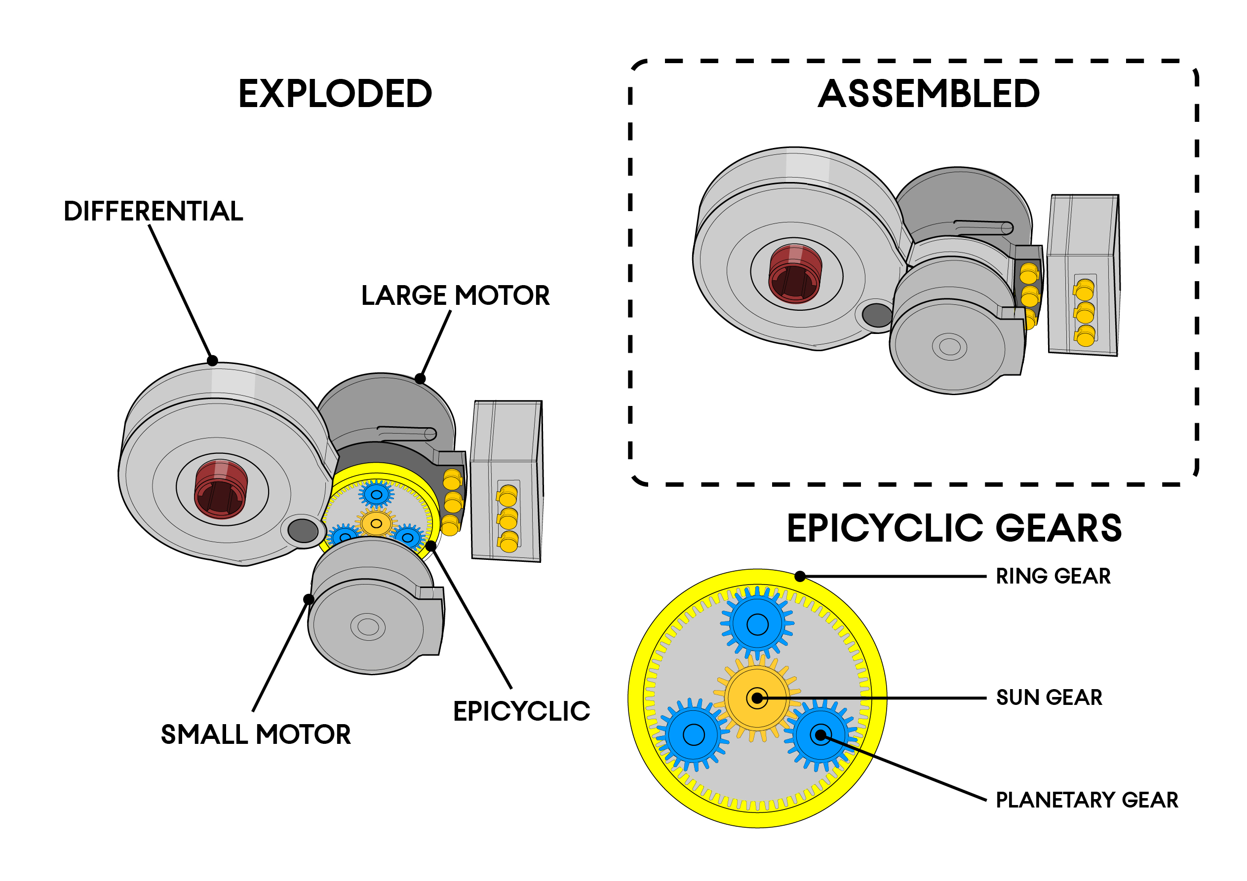
While two motor setups have been employed by other manufacturers in the past, these have motors directly coupled together, with no means to spin at different speeds, which is a common approach with electric motors. It’s the ability to spin the motors independently of each other that appeared to be the issue. Formula E and its manufacturers discussed this potential two motor/epicyclic approach and, accordingly, the rules have been changed from Season6 to ban any potential to exploit this sort of set up.
Having 200kNm of torque available at the exit of every slow corner, one issue for Formula E cars is traction. As with most FIA motorsport categories, Traction control is banned and Formula E limits high-frequency wheel speed measurement in order to control it. But as has been seen in nearly every other FIA category, teams will try to find a way to enact a legal means of traction control. In Formula E there has been a lot of finger-pointing between the teams.
If you cannot measure wheel speed accurately at the wheels, then another means would be useful. Curiosities were raised when some teams appeared with markings painted on the inside tyre walls. It was believed wheel speed could be monitored by cameras measuring the markings moving at speed. Such markings were removed and haven’t returned since.
Another means has been to look at driveshaft torque measurements, as the car accelerates the driveshaft twists slightly and this torque effect can be measured. During acceleration, the torque curve should rise uniformly, as any sudden reduction in torque could be wheel spin. With a closed-loop traction control system, this could be the feedback for cutting power to allow the tyres to regain traction. Driveshaft torque sensors remain a sensitive subject within Formula E.
If a closed-loop system cannot be exploited, then certainly open-loop systems can. The key means appears to be with pedal maps. A pedal map is the software matrix that decides how much power to deliver for a given pedal movement. These can be aggressive or soft, with hot sticky tyres on good tarmac, the driver can exploit an aggressive map, getting lots of power down to the track quickly. In the wet, you’d want a soft map, lots of movement on the throttle pedal for little change in power, to perfectly judge how much traction you might have.
In Formula E, teams were starting to develop maps at the track that match the prevailing conditions, such as tyres, track surface and weather conditions. The driver would then have a map suited for the circumstances and be less likely to overstep the traction available. With several map options available from the steering wheel dials, this presented as a driver aid and the sport stepped in to control it, by homologating the map, with a ‘joker’ option to change the map through the season.
SEASON 7 REGULATION CHANGES
Formula E Season 7 aims to return to a full calendar, again spanning the most glamorous city centres around the globe. As with every season, small technical sporting changes are made to the rules and this season is no different.
Weight
Formula One made the sensible move a few years ago to remove the driver’s weight from the total car weight, now Formula E has gone the same way. At the moment, the total car weight of 903kg includes the driver, lighter driver’s cars are easier to meet the minimum weight limit, or they can have more ballast placed anywhere on the car for a small advantage. Now the driver in their full race kit and their seat must weigh an easily achievable minimum 80kg. Where the driver or seat is lighter, ballast must be added to the specially adapted seat, negating any advantage for lighter drivers.
Motor
As explained above, the two motor\epicyclic setup was already been banned for Season 6. Going further on the same philosophy, now variable inertia motors are banned too. It’s possible that additional energy storage in kinetic form could be exploited with a single motor. So this aims to stamp out any further controversy and limit energy recovery to the electric form measured at the battery.
Furthermore, the motor is now capped at 100,000rpm and additionally, there are new technology restrictions on the bearings used within the powertrain. With inverters sourced from third parties, teams will not be allowed to have exclusive rights to them, so that other teams may also be able to purchase them. If the team creates its own inverters, it retains the right to have exclusivity to them.
Telemetry
From day one in Season 1, Formula E has capped the team’s ability to log and broadcast telemetry data. To further cap costs from the team’s exhaustive data analysis, fewer sensors can be recorded, although the VCU can still present the other sensors data to the driver on the steering wheel display.
Now only data from these sensors can be recorded; brake pressure/temperature, suspension movement, one 3-axis accelerometer, one gyroscope, gearbox shaft speeds, motor/gearbox temperature/pressure, motor speed, tyre pressure and auxiliary battery temperature. This means traditional channels are banned from the data acquisition system, wheel speeds, aero pressure, driveshaft torque, RESS voltage/current, driver steering wheel settings and brake/throttle pedal movement.
Software
Meanwhile, the software package for the VCU is also being restricted to prevent changes at the event and subsequently reduce in-season development costs. For Season 7, the VCU software must be homologated seven days before each event. For subsequent seasons, the software spec for the entire season is to be declared before the championship starts.
Software is not alone in being restricted; the car’s hardware is also being limited. Already the core parts of the powertrain are limited, this goes further with the VCU, Steering Wheel, DCDC, powerbox and Brake by Wire units being limited to two per car per season. Then the carbon rear casing, radiators, are capped at three, with just six driveshaft sets to last the season.
Bodywork
Lastly, even the bodywork is limited – this being a greater risk from race damage, than reliability issues for the car’s powertrain hardware. Now, each driver has just 4 of the vulnerable front fenders, 3 side crash fairings and sidepods. While five floors sounds reasonable, especially with the underfloor skid plank being there to help protect the carbon underfloor, kerb and crash damage can soon render them unserviceable.
Drivers will need to be aware that aggressive racing, taking liberties with kerbs and all or nothing qualifying laps will come at more of a cost than simply a lost race result. Over the season, penalties will be incurred if the bodywork stockpile is depleted too rapidly.