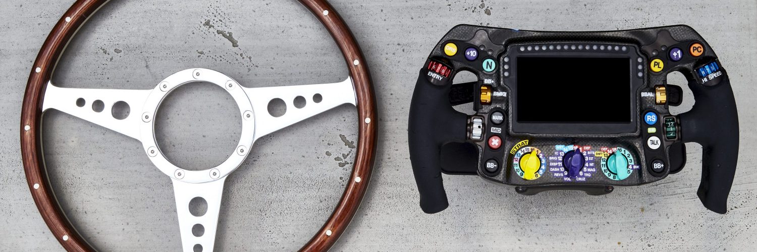
Steering wheels have been called just that, ever since cars first took to the road for exactly that reason, a round wheel used for steering the car.
Much of F1’s history follows this terminology, but as electronics, then latterly hydraulic control of gear shifts and clutch having become ever more important, this has changed. The ‘wheel’ is now anything but round, its primary function blurred between steering and controlling just about everything else on the car with over 180 different switch positions.
In the earliest years, the wheel was round and made from aluminium with a wood rim. But as the years progressed, leather trimmed rims, then suede have added grip, diameters have shrunk and the shape morphed into anything but a round wheel. The spread of electronics in the eighties saw buttons added to the wheel. Then, in 1989, with Ferrari’s introduction of the semi-automatic gearbox, paddles for gear shifting were added behind the wheel. Next, hydraulic clutch control allowed clutch control paddles to be fitted to the steering wheel and the driver’s job was made easier with the footwell having just two pedals.
In the mid-nineties, digital dash displays were fitted directly to the steering wheel and little else in the way of driver controls remained attached to the cockpit – everything was on the wheel. With the post 2014 advent of brake by wire control, even the brake bias control can now be managed from steering wheel buttons.
As we come to close the second decade of the 21st century, all F1 steering wheels have carbon fibre construction, silicone grips, colour screen and an array of buttons and paddles to control everything on the car.
CURRENT STATE-OF-THE-ART
Construction
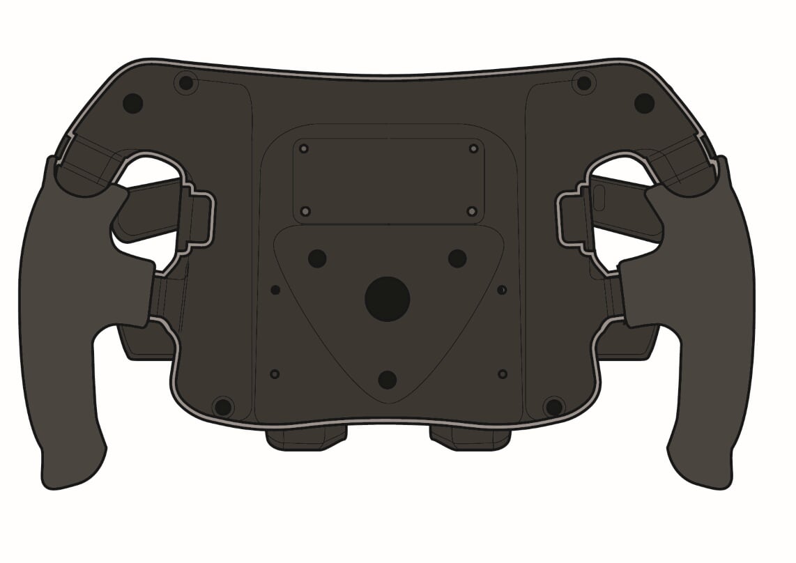
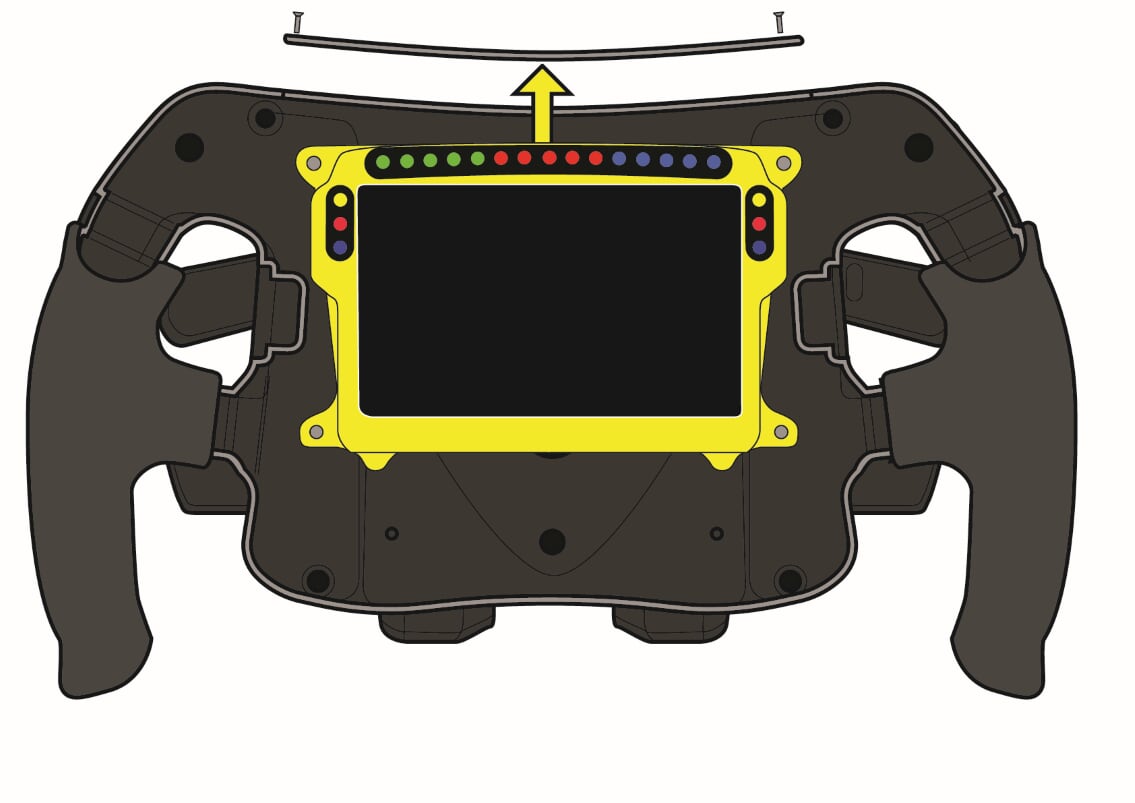
For lightness and strength, the entire wheel is now made from carbon fibre. This is a hollow shell that forms the grips and houses the electronics and the connection to the steering column. It’s made as strong one-piece carbon fibre moulding, with minimal opening to allow the dash, buttons and electronics to be fitted inside. On the Mercedes steering wheel, illustrated here, the dash is inserted through an aperture in the top face that’s then closed with a screw-on panel. The buttons and rotary controls are fitted to separate panels that are bolted in from behind. These panels are 3D printed from a plastic material, a typical application for this manufacturing technique in F1.
 When being assembled, the switches and wiring loom will be installed first and connected to the interface unit, before the mounting panels are bolted in and the dash installed.
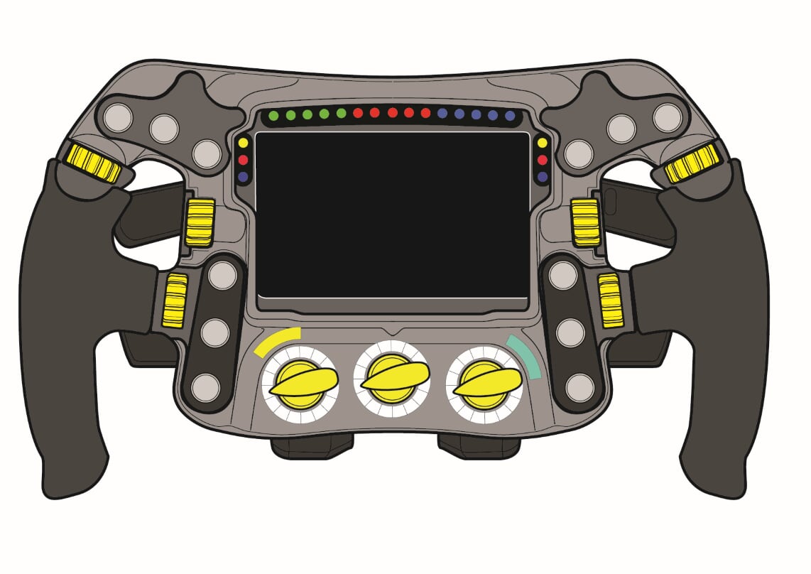
Grips
A neat modern change is the switch to silicone grips for the driver’s hands. The wheel will be inserted into a mould and the silicone injected into the void between the wheel and mould to form the coloured handgrips.
Connection to column
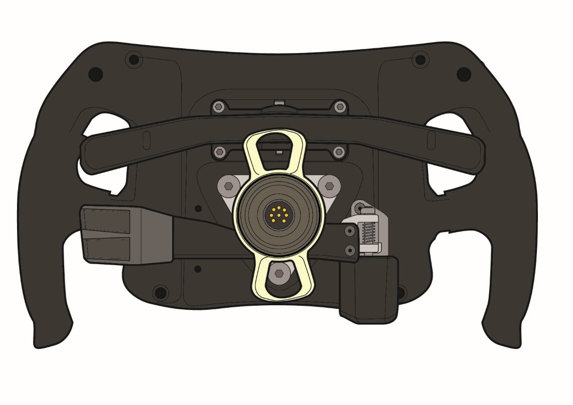 Since the eighties, the confines of the cockpit have necessitated the removal of the steering wheel to allow the driver to get in and out of the cockpit easily. So, a quickly detachable (QD) mechanism is used between the wheel and the steering column. The end of the steering column is splined and has a groove machined around it, then the QD mechanism engages with matching splines to fix it in the 12 o’clock position. Then sprung ball bearings engage into the groove to prevent the wheel inadvertently slipping off. To release the wheel, the collar on the QD mechanism is pulled, which releases the pressure on the springs on the ball bearings and the wheel can be pulled off the column.
With increasing amounts of switches being added to the wheel, there also needs to be a way to connect them to the car’s main wiring loom. This is also done through the QD mechanism. A special connector is built into the end of the steering column and a corresponding connector in the QD mechanism, which couple when the steering wheel is slipped onto the steering column. As the splines on the column end ensure the wheel can only connect in one position, so there is no danger of the connectors misaligning as they connect.
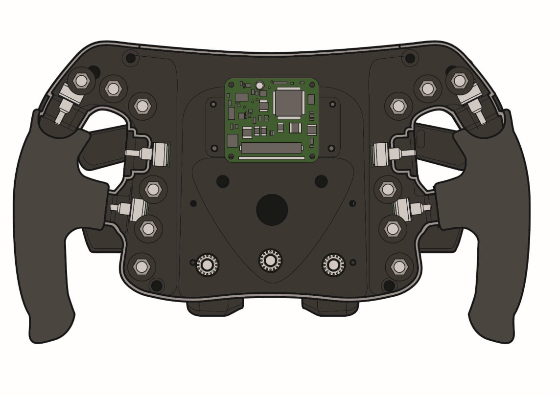
Buttons
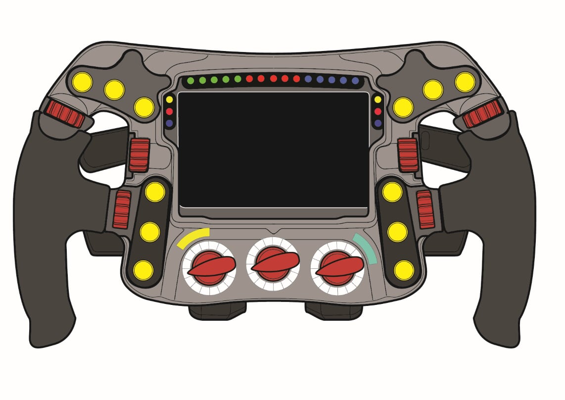
 The button switches are the most numerous controls on the steering wheel, there being a limit to number, but 14 switches are evident on most steering wheels. These are inserted into the fascia of the wheel and bolted in from behind, and from each switch there are two wires.
Most buttons are simple on-off momentary switches, any latching to keep a function on is done by the software, not the switch hardware. Some teams do use toggle switches. Ferrari, in particular, uses them with two behind the top of the steering wheel. In the past, both Ferrari and Mercedes have used them for the race-start setting. If the driver forgets to turn off any toggle switch, it must be done manually and not via software control.
Rotaries
 Also limited by the regulations and hardware are the rotary controls. There are a maximum of nine rotary switches, with up to 16 positions. Each rotary gets assigned a group function, so one may control the engine, another the differential or chassis systems etc.
With so many rotaries on the steering wheel, and some of them being used through out the lap, there isn’t space on the fascia to mount them all. Typically, three are fascia mounted. As with the buttons, these are inserted through the fascia and bolted from behind, then a control knob fixed to the switch’s shaft. The other rotaries are set into the spokes of the steering wheel, which need to be positioned and bolted into the carbon shell before more 3D printed panels are fitted to cover any openings.
Each individual position of the rotary switch produces an output from the corresponding contact at the back of the switch. With nine 16-position rotaries, each having a common power cable and 16 output contacts, there could end up being 160 wires bundled inside the steering wheel, so the rotary switch is capped with a small interface board that reduced to the wiring to just four cables per rotary.
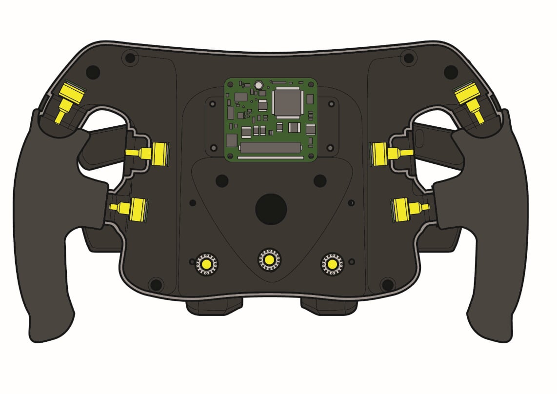
Paddles
The other important controls are the paddles behind the steering wheel, which vary in function and, as a result, vary in the sensors required to control them.
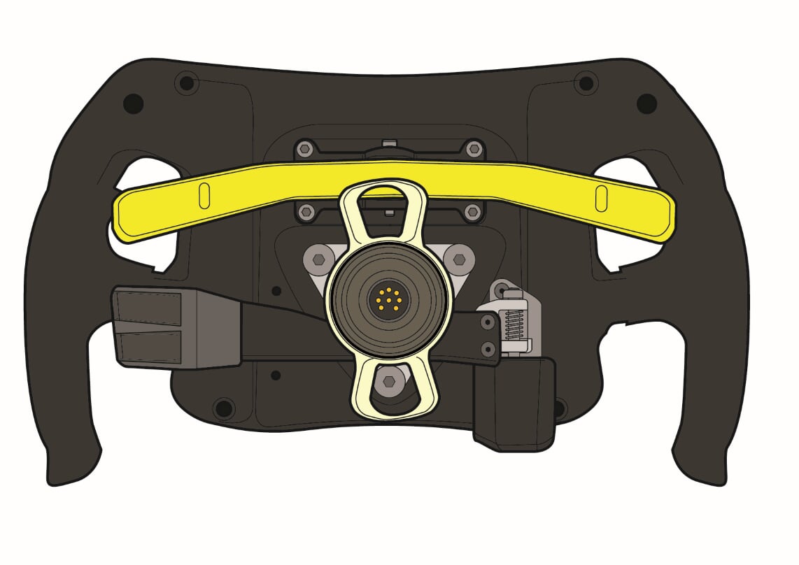 Firstly, there are the gearshift paddles, one for upshifts and one for downshifts – although often one rocker paddle allows the driver to up or downshift with either paddle tip. Paddle position, design and material varies by team and even driver. Even if there’s one rocker paddle, there will be more than one sensor, one for each action. In the early days, these sensors were hall effect triggers, a sensor on the wheel and a magnet on the paddle would switch when in close proximity as and when the paddle is pulled. Nowadays, it tends to be momentary microswitches inside the wheel pressed by the paddle as its pulled.
The paddles have heavy return springs and tiny rubber bump stops to control the paddle movement. The heavy springs are used to prevent inadvertent operation over bumps, while the bump stops and click of the microswitch are used to give a satisfying positive feedback through the driver’s fingers that a shift has been requested. Constructed as one assembly, the paddles, pivots and springs are bolted to the back of the steering wheel.
The other paddles are for clutch control. Typically mounted low down on the steering wheel, there are one or two clutch paddles on the wheel.
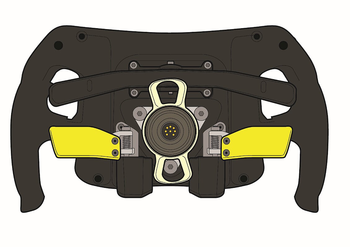 As these need to control the clutch movement throughout their movement, they need a different sensor, not simply an on-off, but require an analogue output. So, a rotary sensor is used at the pivot point that gives the ECU the constant position of the paddle in real time. One sensor is used for each paddle, if two paddles are used. Like the shift paddles, the clutch paddles are quite stiffly spring to give enough resistance to modulate the fingertip control of the movement but not so much as to make it hard to control. Paddle design varies enormously between teams and drivers, with either one long paddle or two smaller paddles. Paddles can be made in aluminium, carbon fibre and often with 3D printed finger grips. Again, the entire assembly is bolted to the back of the steering wheel.
Other paddles may be used according to team\driver preference. This can be for DRS, overtake modes or any mix of the steering wheel’s other functions. Paddles are often used over buttons for these purposes, as it’s easier for the driver to pull a paddle than find a specific button on the front of the steering wheel in the heat of the moment. In these applications, the paddle design is suited to the driver’s needs, often mounted above the mid-positioned gear shift paddles and using one of the button-switched outputs, repositioned from the front to the rear of the wheel.
Mercedes have famously employed the ‘magic paddle’, which is a combination of functions to provide maximum performance for overtaking. Ferrari’s Sebastian Vettel had a secretive extra paddle, which was widely believed to be a ‘hand brake’ using the car’s brake-by-wire system to hold the brake on at the race start. This paddle subsequently disappeared, and an even more secretive button used at the race’s start. This button being hidden underneath the silicone hand grips, it was not visible externally, but could be covertly operated when pressed through the flexible grip material. Its function isn’t confirmed, but is probably linked to the race-start power unit mode.
Lights
As well as the steering wheel having inputs from the driver, it can produce outputs to the driver, so there are a small number of LED lights allowed to be used in addition to the dash display. Drivers will use these as signals for DRS, ERS usage and other power unit functions.
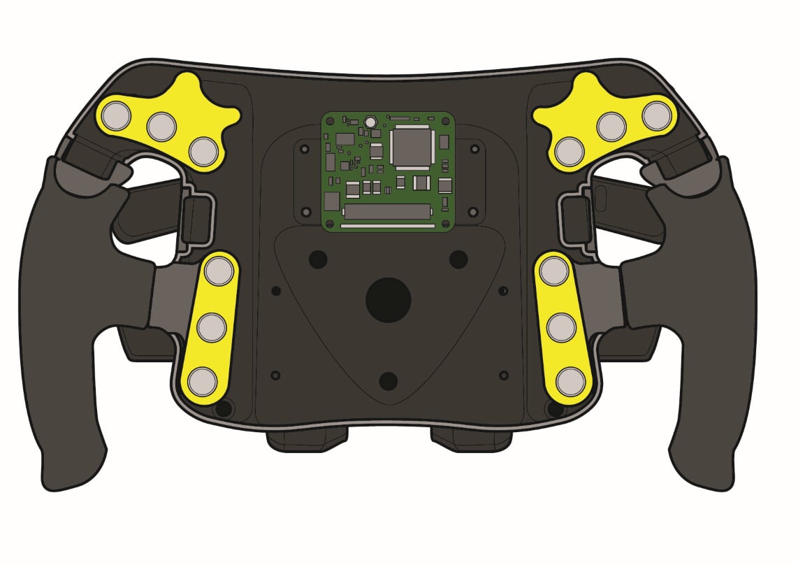
Interface unit
With the 9 rotary controls, 14 switches, six LEDs and various paddles, there is a huge amount of potential cabling that needs to talk to the car’s ECU mounted in the sidepod. This would be a huge task to fit into a slim steering wheel shell, let alone down into the narrow steering column. Luckily, F1 cars do not run a simple cabling system but a CAN BUS set up. This is more akin to a computer network than a point-to-point wiring set up. Thus, the complex wiring inside the wheel can be reduced with an interface unit that combines the 196 cables and outputs with just a few cables.
Dash
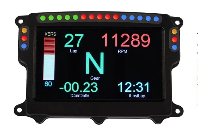
The FIA enforces a single supply of Dash displays, with McLaren Applied Technology supplying the current unit with its colour LCD screen. This unit interfaces via the CAN BUS to the car’s ECU, from which it gets its information to display on it 4.3 inch screen. As well as over 100 configurable display pages, the dash also has lights for gearshift and ERS use, as well the mandatory FIA marshal warning lights. These flash the colour of the prevailing warning flags to the driver.

Remarkable! Its truly remarkable post, I have got much clear idea on the topic of from this article.
bookmarked!!, I love your web site!