Some eagle-eyed observers of the Canadian Grand Prix weekend may have noticed Mercedes in a race against time to fix a hydraulic leak on Lewis Hamilton’s car before race day, the leak discovered on the champion’s car on Saturday night.
Mercedes being Mercedes, the engineers got to work and removed Hamilton’s engine and floor to rectify the problem and all was right in time for race day.
During race commentary, there is often the mention of hydraulics and hydraulic problems, and yet this complex area is rarely fully delved into. This isn’t the brake hydraulics, nor the hydraulics used for the passive suspension, rather what the teams call ‘Control Systems’.
These have been in F1 since 1983, with testing preceding over a year before that. Back then, it was Lotus using hydraulics to actively control the suspension using aircraft-based hardware, as the need to control flying surfaces is effectively the same engineering solution as controlling suspension. This technology has subsequently been applied to many other systems on the car and nowadays every F1 car has a complex hydraulic control system, used to operate nine sub-systems on the car. From a clunky and unreliable arrangement, hydraulics has matured into a robust and dependable system.
Why use control systems?
Historically, the driver has been the main ‘control system’ – the driver’s timing and effort to operate the powertrain was part of their skillset and separated the good from the bad. It was the driver’s dexterity and co-ordination that sequenced upshifts and ‘Heel-and-Toeing’ through downshifts. Yet every driver is fallible and there’s only so much a driver can do alone in the car. With the advent of Electronics and the arrival of the ECU in the early eighties, engineers had a tool that could think faster and operate things in a way that a driver simply couldn’t. It was a while before hydraulics was employed for more than the Active suspension systems, but the lessons learnt, and the hardware onboard, was soon exploited by the engineers.
Ferrari jumped first with John Barnard’s semi-automatic gearbox, using the hydraulic hardware to shift the gears in 1989 with Nigel Mansell and Gerhard Berger experiencing degrees of success and failure with the early system. Thereafter, teams applied the technology to throttle and clutch control and, suddenly, anything could be reliable and precisely controlled via the ECU with these hydraulics. Although there was the ban on active technologies in 1994, the control systems were retained and F1 has never been without them ever since.
Now a driver simply couldn’t miss a gear and didn’t need to blip the throttle on downshifts. Additionally, the steering could be power assisted, the clutch could be operated by a hand on the steering wheel, the differential could be set up to change settings as the car goes through a corner and systems such as DRS were possible.
Why hydraulics?
When teams were first adopting semi-automatic gearshifts, Hydraulics were not the only solution. Tyrrell initially developed a pneumatic system, but this was soon phased out as hydraulics proved to be the better solution. The key performance required from a control system is power, which brings force and speed to the control operation. Electrics and pneumatics can be configured to bring this level of performance, but Hydraulics provide this in a smaller envelope. It’s the power density that sees hydraulics as the primary solution, packaging the pumps, servo-valves and actuators into a smaller space. The downside is the weight can be higher, the cost is higher, and power is taken from the engine to drive the pump. Iterative development work has brought the weight down and the parasitic losses from the engine, while F1 has never had an issue with spending money on the right solution!
System outline
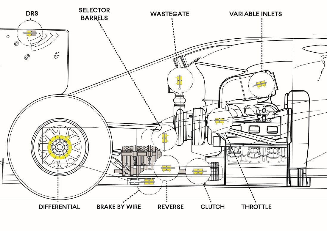
The entire control system hinges around two factors – the control valves and the oil pressure.
Control is provided by the servo-valves taking input from the ECU and converting them into changes in hydraulic pressure. The output from the valve is translated into movement by pressure acting on a piston inside a cylinder and pressure in the hydraulic fluid comes from a pump driven off the engine. Amongst all this, there is a maze of pipework and manifolds to direct the pressurized fluid to the servo-valve/actuators dotted around the car. The fluid then needs to return to the pump once it’s served its purpose.
Currently, the Hydraulic system controls the following functions:
- Power Steering
- Gearshift
- Clutch
- Differential
- Reverse gear
- DRS
- Brake by Wire
- Throttle
- Inlet valves
- Turbo Wastegate
Previously similar control also managed the suspension movement, rear wheel steer and fuel flap.
Servo valves
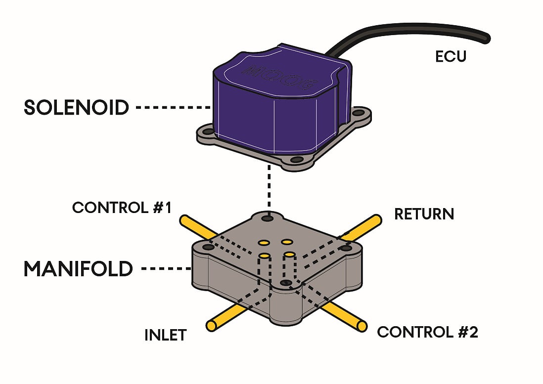
As is the case with aircraft, the servo-valve is the key solution in this system. It’s a precision engineered part, that can reflect small electronic inputs with proportional changes in pressure output. Moog is the company that universally make the servo-valves for F1, so they are often simply termed ‘Moog valves’.
Control is achieved via the DC output from the ECU controlling a solenoid inside the servo-valve, which in turn moves the internal spool valve to and fro. It’s the movement of the spool valve that sends pressure to one of two outlet ports, with a drain port allowing fluid pressure to escape and re-centre the valve.
As one valve can control two movements, for most functions the one valve works on a double acting piston/actuator to finely control the movement back and forth. For some simpler functions, one valve can be used for two systems, as long as they are not active simultaneously, hence DRS and reverse gear are controlled in this format.
By regulation, the steering control cannot be achieved with an electronic valve. Instead, there is still the spool valve, but that is moved mechanically by the torque put through the steering column. That then alters the pressure to give the steering power assistance.
Hydraulic pump
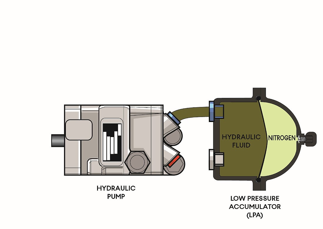
To enable the force to operate the control functions quickly, there needs to be a high fluid pressure in the system, which is provided by a special pump attached to the engine. Needing to deliver some 250bar of pressure, a small but robust pump developed from the aerospace industry is employed. Although other manufacturers do produce such pumps and have supplied F1 in the past, Parker Haniffin have been the preferred supplier for most teams since the nineties, with one specific pump model being used throughout this time.
This pump sits down amongst the water and oil pumps on the side of the engine. Before 2014, with the V8 engines, it was positioned on the left. With that space now occupied with the MGUK, nowadays this is on the right side of the engine.
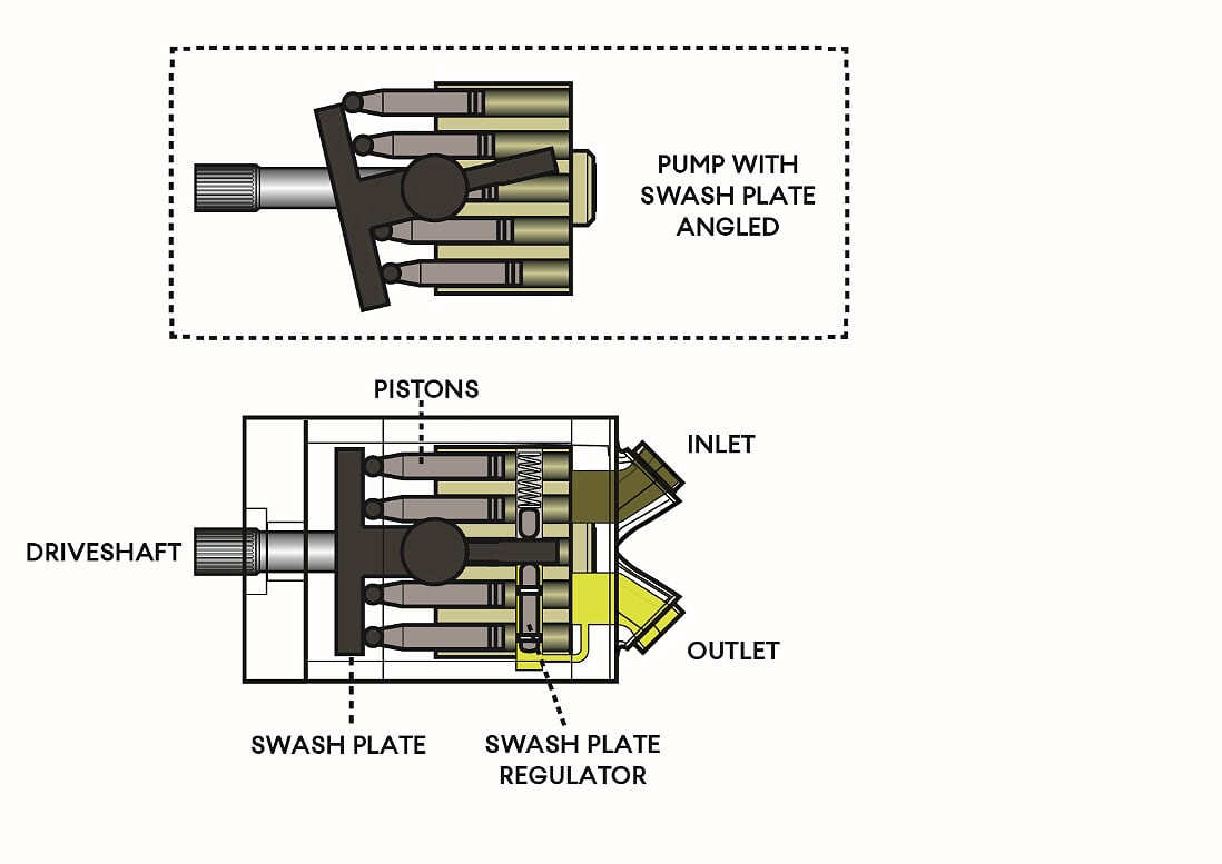
This now ensures the pump needs to deliver the 250 bar pressure at any point around the lap, regardless of engine speed. This is to prevent no-pressure at tickover and over-pressure at high RPM, so the pump has a swash plate set up. Similar to a helicopter rotor, the internal pistons are mounted on a swash plate that swivels to maintain a consistent oil pressure as RPM increases. Swash plate movement is controlled by the pump’s own oil pressure, and as the pressure output rises, the swash plate tilts to reduce the piston strokes and automatically regulates the pressure it delivers.
Weighing about 1kg, the pump is quite heavy in F1 terms, but the main issue is the power the pump saps from the engine. Back in the nineties, this was a considerable amount. But development to the pump itself and the demand from the control systems will have reduced that over the three plus decades of hydraulics in F1.
Hydraulic fluid
Fulfilling the role of transferring the pressure from the pump to the actuators is the oil-based fluid that fills the system. Albeit dyed red to help identify it apart from other fluids should there be a leak, it is essentially the same as brake fluid. Thus, F1 hydraulic fluid has some of the same issues in use, particularly with contamination and temperature.
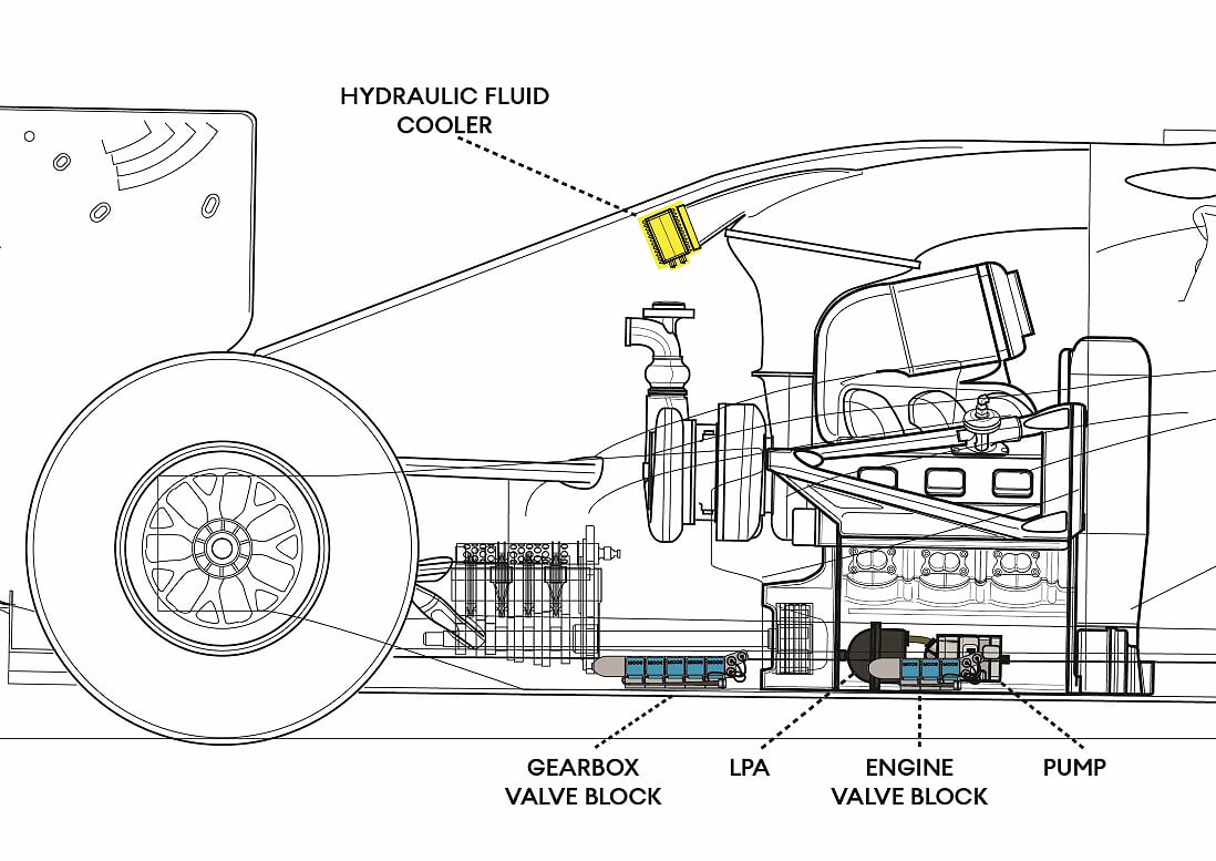
The earliest F1 hydraulics were open systems and thus the fluid was exposed to air, which created issues with bubbles forming in the system from air absorbed by the fluid. Even with the constant volume closed systems used now, there can be problems with air dissolved in the fluid forming bubbles if the pressure drops to atmospheric. This affects the fluid that is coming from the high-pressure side of the system and collecting in the tank before returning to the pump to be re-pressurized. To prevent this, the fluid in the low-pressure side of the system is kept lightly pressurized to above atmospheric, by being stored in an accumulator. This Low-Pressure Accumulator (LPA) is a small tank that keeps 100-200ml of fluid kept under 3-5bar pressure by nitrogen gas, there being an internal bladder separating the fluid from the nitrogen.
As the system is compact, there is only some 800ml of fluid in the entire system, which means that heat soon builds up in the fluid. This heat comes from the compressing effect of the pump, the fluid movement through the valves\actuators and the hot environment underneath the bodywork. To keep the fluid at working temperature of 120-140°c it is cooled by a small heat exchanger in the return circuit. This is typically mounted behind the engine and will receive cooling air usually from the roll hoop inlet.
With the danger of air, water or other contamination affecting the fluid should the system be opened to the atmosphere, maintenance of the system is carefully controlled. Before use, the system will be bled of any air trapped in the pipework and then flushed with fresh, uncontaminated fluid. This process is completed, with a dedicated rig shipped to every race and kept within the pit garage. Once this is done, the system is kept sealed and will not be opened unless essential.
Valve blocks
Making maintenance easier, the installed system is broken down into sub-assemblies, which are pre-prepared in the clean confines of the factory. These sub-assemblies are designed to house everything for one section of the car, known as valve blocks. There will be one Power Unit block, a Gearbox block and a separate section leading to the steering rack.
A typical valve block is be a complex part, machined from aluminium, with internal drillings to send the high-pressure fluid from the inlet, to the servo-valves and back to the low pressure return. Being subject to high internal pressures, they are carefully designed in CAD and Finite Element Analysis (FEA) to ensure they are light but can cope with the loads applied to them.
Accumulators
Valve blocks also feature additional accumulators, which are slightly different to the LPA as they handle high pressure fluid. Such High Pressure Accumulators (HPAs) have two functions; the first is to provide flow when demand is high, such as when a valve opens to supply fluid to an actuator. The second is to smooth out pressure variations delivered from the pump, as the pump doesn’t deliver a smooth and continuous pressure.
There is another accumulator in the system. This is used in case the car stops on track and the driver or marshal needs to select neutral to allow the car to be moved. So, there is a special tank containing enough pressurized fluid to disengage the clutch even if the pump has stopped. Known as the Clutch Disengagement System (CDS), it is activated from the button on top of the chassis marked “N”. Disengaging the clutch is a simpler solution than trying to engage neutral on the gearbox.
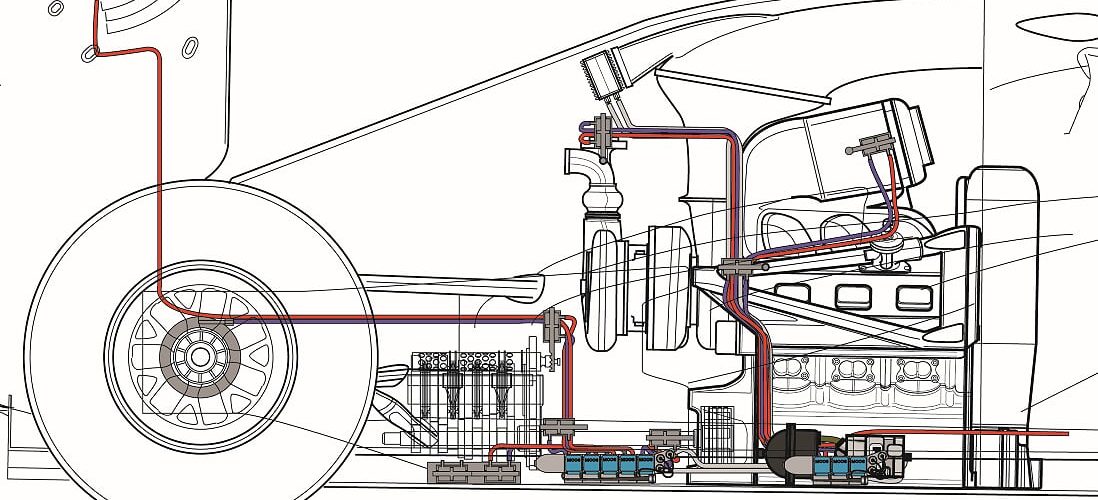
Once built, these sub-assemblies will not be opened up in the field to avoid contamination. Instead, replacement sub-assemblies will be fitted to resolve any problems. Installed on the car, they are linked with dry-break connectors so that any removal of the engine or gearbox does not automatically mean a bleed/flush process is required. However, should the system fail and the fluid leaks, then the full bleed/process will be required to ensure the system’s integrity.
Pipework
Distributing the high-pressure fluid from the pump to the valve blocks and onto the actuators, is achieved with either rigid titanium pipe or braided hoses where flexibility is required. These connect with special fittings, using ‘O’ rings to seal the connection and a K-nut\flange to secure the connector in place. Every pipe is fully designed in the team’s CAD system, the drawings for this will be used in the pipe being machine and jigs to create the finished pipe. Once bent titanium pipe cannot be adjusted to perfect the fit, so there is only one chance to bend each section of pipe.




Love Diagrams and all about them !