There are very few cars that have comprehensively dominated an F1 season and when they do, often it’s these cars that have some key innovation that steps them above their peers.
Something so advanced and ingrained into the car’s design that it simply isn’t possible for other teams to catch up with their own innovations or even to copy the lead team’s ‘tech.’ Most notably amongst these F1 ‘game changers’ is the Williams FW14B. Its speed came from its aerodynamics, but only because they were underpinned by the active suspension and powerful Renault engine.
None of the features were individually new or innovative, but the fundamental concept and the engineering that went into making them work was what made the car a very special one.
The genesis of a new era of F1 tech
First of all, let’s set the scene for the 1992 championship. For some of us, the events leading up to that year seem like yesterday, but they are in fact now over thirty years ago!
McLaren had been the dominant team who emerged from Williams’ previous success with the Honda Turbo. At this point there were 16 teams entered into the world championship. This was at a time that a small operation could buy a reasonably affordable customer engine, a gearbox and build up a chassis.
But, as budgets and team sizes started to escalate, this was also the start of the modern technical formula, teams were committing considerable effort to wind tunnel programmes and starting to evolve the manufacturing of the car to include more composites and more in house development of suspension, gearbox and electronics. Formula 1 had emerged from the turbo era and the 3.5l multicylinder engines were the incumbent format, either as a V12 or Renault’s V10, whilst most other teams had either the incredible Ford Cosworth V8 or lesser revving V8s from Cosworth and others.
Aerodynamics and car philosophy was becoming something more sophisticated, the use of wind tunnels and their increasing predictability to the real world meant that cars were no longer designed, built then run – now a simulation/validation loop was inserted between design and build. This rigour meant that teams were gaining an increasing understanding of aero and how it applied to the open-wheel low-slung F1 car.
By the early nineties, the car had a flat bottom between the wheels (no step, no plank) and large wider diffuser at the back of the floor. Teams had started to exploit the underfloor, with lower and lower ride heights to the point that suspension control was critical in managing the small gap twixt track and car. Meanwhile, other areas of development were opening up, mainly being the raised nose and the understanding of front tyre wake impinging on airflow downstream on the car.
For Williams, there had been a quiet spell in their success in F1 for a few years. The loss of the Honda turbo engine led them to an underpowered Judd V8 engine in 1988, attempting to use their active suspension to maximise their aero whilst overcoming the lack of power against the turbo engines. Then in 1989/90, without the active setup, but with the new Renault V10 engine, they had some success with the Enrique Scalabroni designed FW13, under Patrick Head’s direction.
Meanwhile, Adrian Newey had made a name for himself as an F1 designer at Leyton House March, with the neat and effective CG891/901. Williams needing to up their game, particularly in regard to the key area of aerodynamics, were looking for a new lead designer. The swap over came just as the CG890 came good and the Leyton House operation started to fall apart.
Newey became the new designer and set about working with Williams under Patrick Head to develop their new race car that could exploit the resources Williams had at hand, and with the constantly improving Renault V10. The result was the FW14, that would have its bugs ironed out and evolve into the FW14B to dominate 1992.
Design and Development
Williams operated under the title ‘Williams Grand Prix Engineering’. This rather industrial title also served to highlight the type of team Williams was at this point. A huge factory operation allowed Williams to engineer pretty much any part of the car, not just fabrication and carbon fibre, but also gearboxes and crucially electronics.
On the aerodynamic side, like most teams at this point, Williams used a third-party wind tunnel which was the Southampton University tunnel. But being one of the major players in F1, Williams opened its own wind tunnel at its factory through 1991 allowing the team to increase its use of aerodynamic testing without having queue for time with other teams.
Given these resources, Newey set out a plan for an all-new car, not just for Williams, but a step forwards in F1 design terms. It was clear to Williams that it could develop a solid rolling chassis, that the Renault power unit was amongst the best, but the aero side was still letting the team down.
The earlier use of active suspension was viewed by some outside the team as a failure – in reality it was a step too far too early, compounded by the drain on power the Hydraulic control system drew from the humble Judd engine. In essence the active ride system could maximise aerodynamics, allowing the use of more extreme geometries as the car would remain stable relative to the ground.
Newey’s plan was to bring this all together, cutting edge aero maximising underfloor downforce with minimal ride heights. The gap kept near constant by the active suspension and with the Renault V10 capable of power both er the car and the hydraulic pumps. The Williams team’s ability to support the electronics and hydraulics in house was a huge bonus and allowed the team a head start on its rivals. The hydraulic control system also opened up the option for semi-automatic paddle gearshift, first pioneered in F1 by Ferrari in 1989 and also with Mansell behind the wheel of that beautiful car. This was the start of the active era and Williams were at the front of it.
The FW14B Car Layout
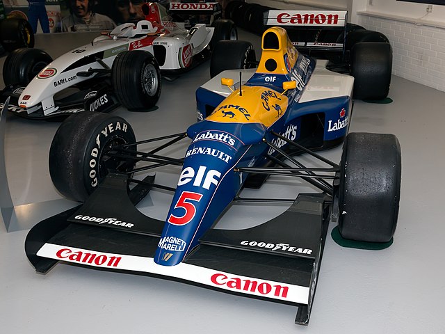
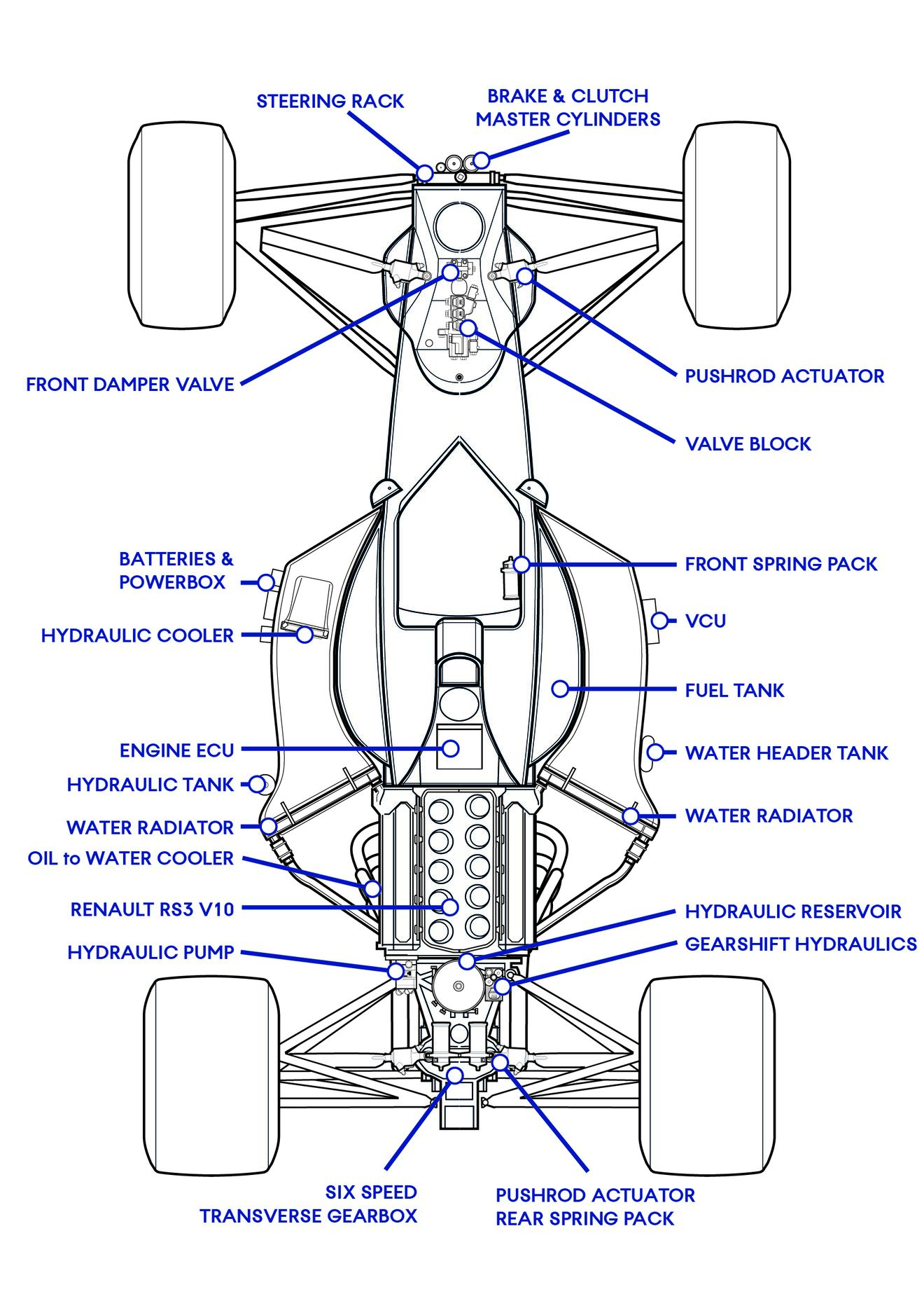
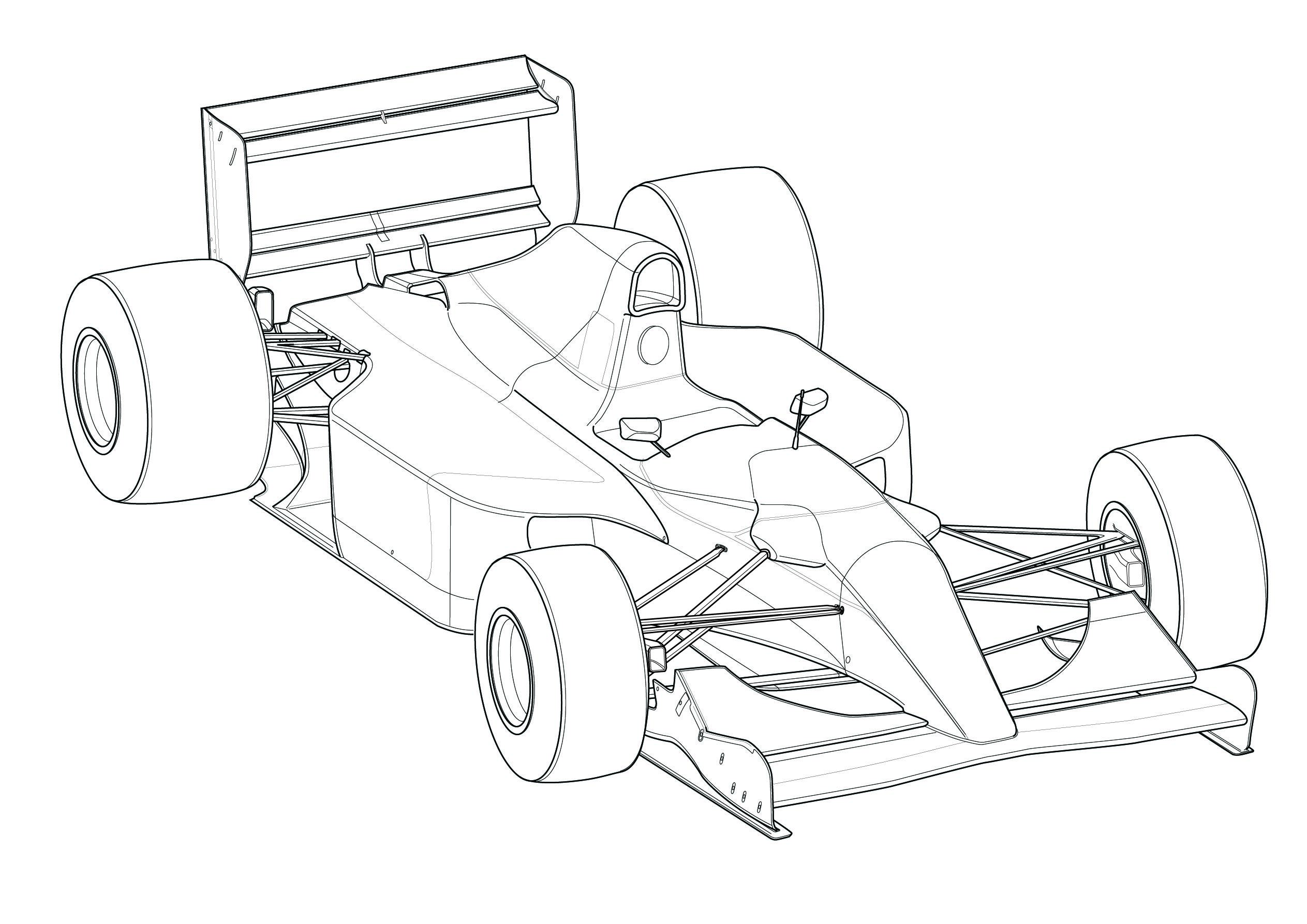
Compared to F1 cars before and after, the FW14B had a conventional layout, with a monocoque housing the driver and fuel, double wishbone suspension outboard brakes and a front nose cone crash structure. Behind this mounted the engine as a stressed member, to which the gearbox case was attached, and the rear suspension picks up on that casing.
What differentiated the 14/14B from the previous Williams was the raised nose. The entire footwell section of monocoque was raised from the ground and the front wing merged into the nose cone, creating a clear path for the airflow to reach the underfloor. Keeping the monocoque stiff was of course its carbon fibre construction, but also Newey’s trademark tiny cockpit opening.
Rules demanded the cockpit had a minimum width and length, but not a template to describe the shape it should be. Thus the cockpit was wide enough but only met the length requirement on the centreline, creating the “V” shape to the front. The cockpit also rose up over the steering wheel streamlining the cockpit, as well as stiffening the structure.
The tighter confines of the cockpit was possible as there was no gearstick to accommodate, a problem usually solved with a large blister in the cockpit side – something Newey had to personally remould when at Leyton House! The small cockpit suited Mansell who, despite his broad stature, still fitted comfortable and usually drove with a tiny steering wheel regardless.
Aerodynamics
Fundamental to the car’s success was its aerodynamics, although outwardly there wasn’t anything overtly innovative or extreme about the shape of the bodywork. With the assistance of the active ride, the underfloor was the crucial area being exploited, a wide flat floor sat below the car, ending with a diffuser curving up below the multi element rear wing.
With such a large flat floor capable of producing huge amounts of downforce, the problem with managing the downforce is the one it creates with variation in ride height. This means the floor running very close to the ground can easily choke if it tuns too close or lose downforce if the ground clearance runs too high.
The variations in ride height come not just with undulations in the track surface, but also with roll in corners or pitch with acceleration/braking. Teams with a more conventional suspension set up have to shape the underfloor conservatively to suit the variation in the ride heights, hence either losing performance in the process or risking big changes in downforce as the car moves about the track. With the active suspension, this sensitivity is negated and the shape of the underfloor can be tailored to suit the smaller range of ride heights in order to gain more downforce.
As the floor/diffuser package creates downforce not just at the entry to the diffuser, but also at the leading edge, the floor needed to be relatively long to balance the downforce created each end. Thus, the sidepods above are longer than their internals needed them to be.
Also in fashion at the time was the exhaust exiting through the diffuser, the mass flow from the tail pipes helping drive flow through the underfloor and create downforce. Although Newey would later reintroduce the blown diffuser concept while at Red Bull Racing, the complex engine mappings that helped it become a success in 2010 weren’t available in 1992. Thus the blown effect was somewhat throttle position dependant and lead to some sensitivity in the balance of the car.
The leading edge of the floor is critical in setting up the creation of downforce under the car, so feeding the leading edge with a clean airflow was a first order problem to be solved. Already Tyrrell had debuted the solution with the raised nose 019 in 1989, Newey was also working along a similar but less extrovert solution with the CG889 car.
For the FW14 the raised nose followed the anhedral wing philosophy, the outer sections of wing creating the load with large adjustable flap, leaving the middle span of nose with less angle of attack to allow an undisturbed airflow to pass through towards the floor.
Also attached to the front wing were elongated endplates that reach inside the front wheels. Contrary to appearances, these extensions were not to help seal the front wing to the ground, but to separate the front wing wake from being impinged by the airflow being pushed around the front tyre. Teams had now started to understand the flow field around the tyre running along the track.
Part of this is the inwash created near the ground from the airflow passing inside the inner tyre sidewall, known as ‘tyre squirt’. This sideways airflow used to upset the airflow coming off the front wing to detriment of performance. These curled extensions caught the tyre squirt and directed behind the front tyre, leaving the front wing flow passing cleaning alongside.
Far smaller than the cooling needs of the old turbo engines, the 3.5l V10 engine still required a reasonable radiator package for the water and oil. Thus, each sidepod packaged a large radiator fed by a long diverging duct – the heat passing out the other side, either exited through the coke bottle shape or through small openings in the flanks of the sidepod.
This radiator positioning worked for a rearwards weight balance, due to the relatively front tyres being raced at the time. As a result, the long sidepod/floor worked to develop a balanced downforce under the car. Usefully the long sidepods provided ample space for the electronic control units, which were quite large compared to modern times.
At the rear, the wing was a more complicated affair than currently allowed in F1. The wing obviously varied in spec according to the circuit, but was also allowed more, with 2-3 top elements and a 2 element beam wing, sometimes with additional elements in between. The wing creates its own downforce, but its mounting position directly above the diffuser sets up a cascade of upwashing airflow from the diffuser, beam and top rear wing. The compound effect of these surfaces in cascade is greater than their individual contributions to downforce.
Active Ride
As explained above, the active suspension was to unlock the aerodynamic potential of the car without sensitivity. It wasn’t merely just to smooth out bumps, rather to ensure that ride height didn’t change excessively in pitch and roll. While the system was key to the car’s huge success, the active system wasn’t new to Williams nor F1. Lotus had pioneered the concept in the mid-eighties, but never found the gains it was hoping for. Williams also raced their system on the FW12, but as described it was not the right solution for the time.
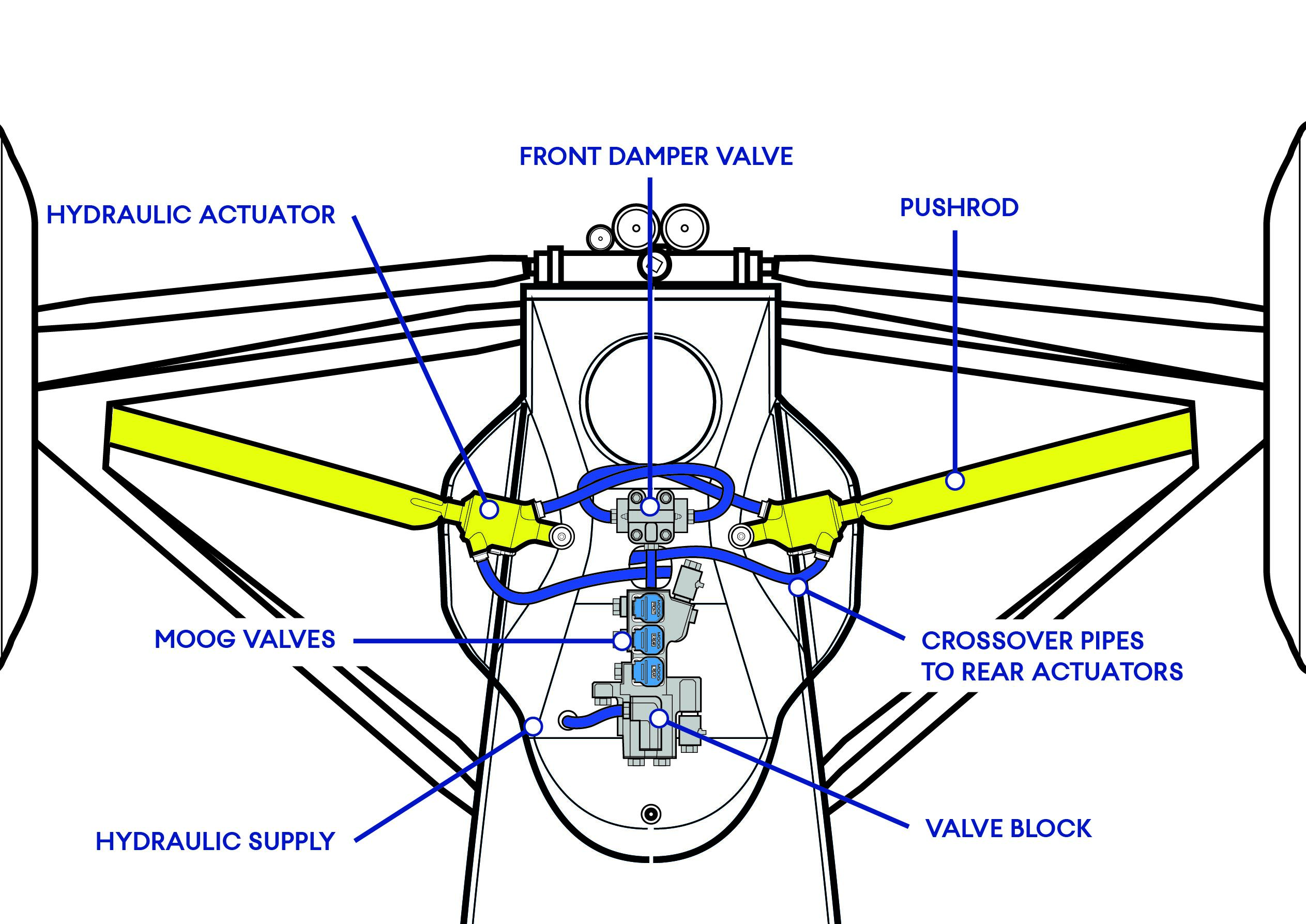
In essence, the system is quite simple – pushrod length could be rapidly altered to maintain a near constant ride height. Using hydraulic pressure graduated by Moog valves under the control of an ECU fed by sensor inputs. It’s often misunderstood that the active system replaced conventional springs and dampers, but this isn’t actually the case. The FW14B retained both, albeit in modified form to the conventions of the time. Thus, the set up wasn’t simply four hydraulic control systems at each corner of the car – and a pump.
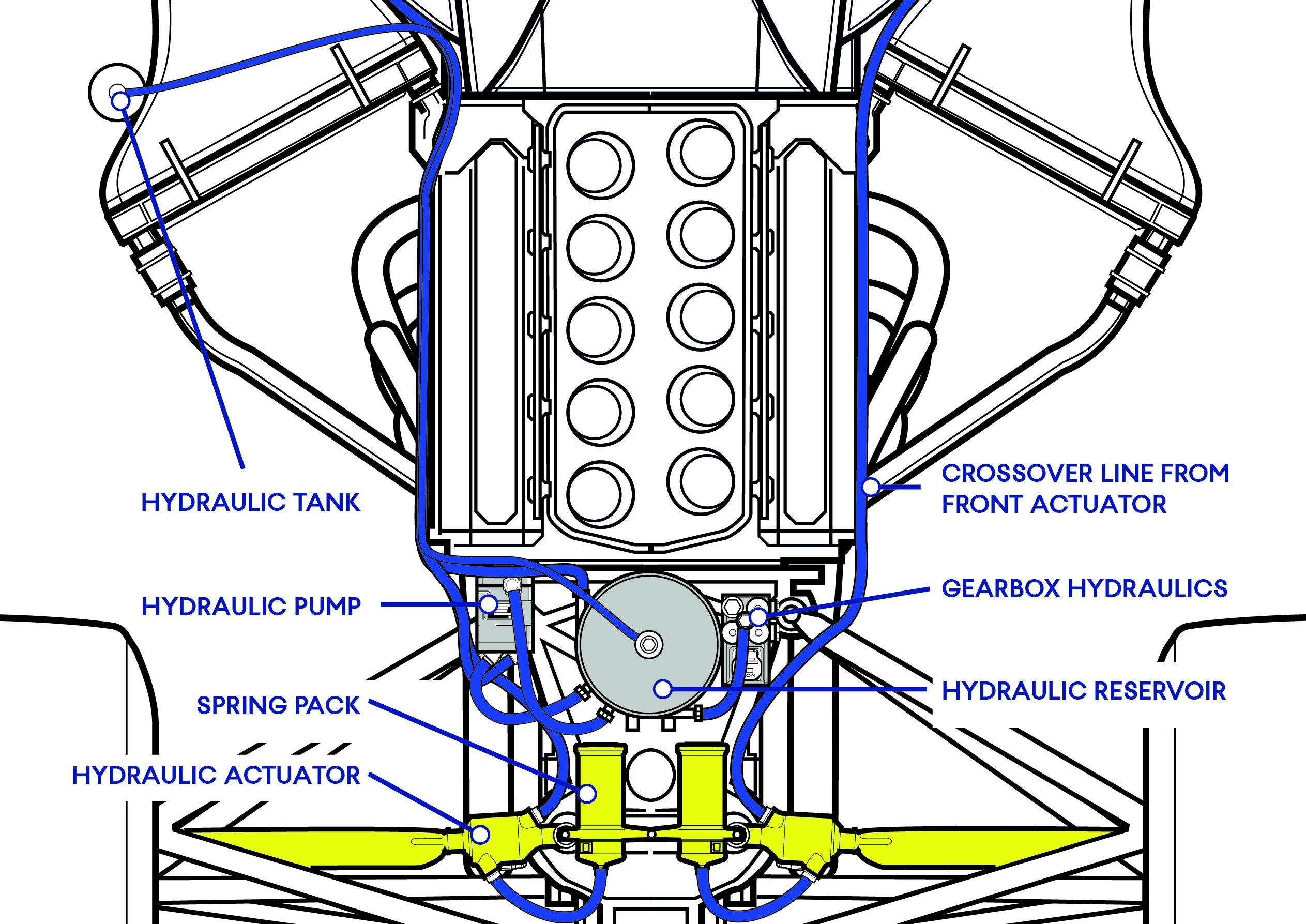
Instead, there was a clever system with three control valves (front pair, rear left, rear right) and cross over piping to provide the car with enough control of pitch and roll at each end of the car. Whilst the hydraulic control hardware was in itself a challenge of engineering on an F1 car, it was the electronics and the software that realised the true potential the system.
Starting with the hydraulic hardware, this relates closely to the layout of current F1 control systems. A pump is driven off the engine, this provides the hydraulic pressure to a valve pack at each end of the car. These valve packs house the control part of the system and Moog servo valves meter the fluid pressure to actuators at each wheel. The actuators are simple piston/cylinder components that move in direct proportion to the fluid pressure applied to either side of the piston.
Although common in aerospace, it was no mean feat to make these systems react and be reliable whilst when being shaken around an F1 circuit. Also, the maintenance of these systems was a new discipline in the pit garage. The hydraulic circuits do not like being de-pressurised and disassembled, thus being exposed to air, dirt and moisture. Resetting the system was a ritual and the cars final bleed and test, was often demonstrated with the car going through a ballet of movements, as each actuator is moved individually and in pairs.
At a standstill, the car was supported on spring packs built into the hydraulic pipework, the rear packs were cylindrical units mounted atop the gearbox, while there was a single front spring pack mounted remotely behind the driver’s seat! Also built into the hydraulic system were damping valves, akin to those used in normal dampers, but it was the active system’s hydraulic fluid passing through them rather than dedicated damper oil.
In this mode, the car was almost a normally suspended car. The use of the hydraulic pressure and Moog valve control ‘simply’ served to raise the car to suit the ride height programmed into the software. To develop the control system, recent graduate Paddy Lowe was hired by Williams. Under Lowe’s development, this control logic quickly matured to allow the aerodynamics to always be at their best, which was the key to the car’s success.
Reading the car’s height was key to the electronic operation. Sensors would detect the ride height and the ECU would calculate the pressure required to bring the ride height back into the correct position. This way the ride was always set at the ideal setting as programmed into the software. As things became more complex the code accordingly made more decisions based on factors such as speed, steering angle, and the setting on the cockpit switches.
An algorithm was calculated for each suspension mode around the track. Fast turns, slow turns, short straights and flat out runs – the driver having a series of rotary dials on a panel in the cockpit to fine tune settings. Also, as well as more conventional suspension modes, the car could operate at some more unusual positions, one of which being to lower the rear end at heigh speed.
This reduced the downforce and drag created by the car, as the underfloor flow stalled and the effect cascaded upwards, stalling the rear wing and the drag it induces as a result. Just such an effect was evident in Turkey in 2021, where the rear of the Mercedes could be seen to suddenly drop as speed increased on the straights.
Knowing the car’s ride height and the intended ride height allowed the electronics to work out something quite clever. If there was a difference between the two, then something must be wrong in the suspension. Williams could see a puncture being detected and, as the deflated tyre meant that the car was running too low for the actuator position, so the puncture warning would flash up on an LED on the dash.
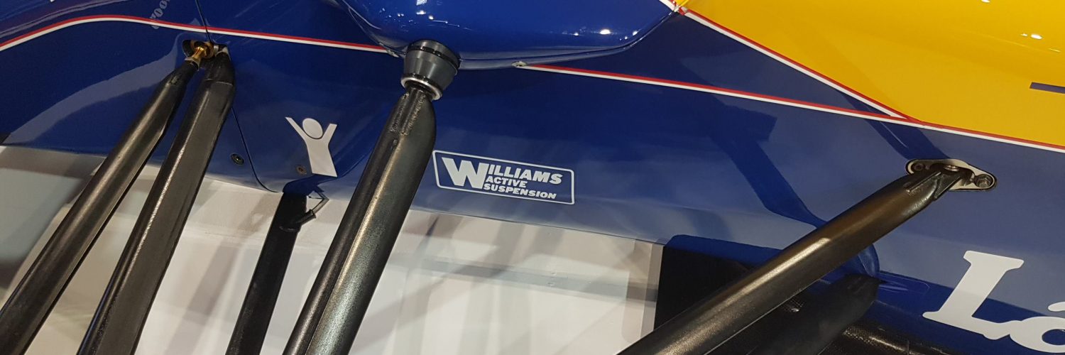
The FW14 ran a near conventional package of the pushrods operating rockers and then the hydraulic actuator. This was simplified on the “B” version, with the actuator being built into the pushrod end, thus simplifying the packaging and creating the distinctive bulged bodywork atop the nose.
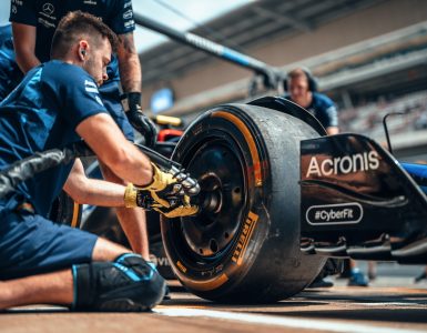
Paddle shift
Having the hydraulic system allowed Williams to also automate the gearshift, which had already been achieved by Ferrari with the F190. Ferrari, under John Barnard’s direction, developed a hydraulic system that could rapidly shift gears controlled from a paddle on the steering wheel.
The first system was unique, using hydraulics and Moog valves shifted each selector fork within the gearbox with a dedicated actuator. This was a clever set up and could potentially allow the driver to skip gears, going from sixth to second without needed to select all the intermediate gears. But the triplet of actuators was complex and unnecessarily heavy.
Williams’ incarnation matched the same approach as other teams (inc Ferrari) subsequently followed, using a motorcycle-style shifting drum and automating it. This required a single double acting actuator that drove the rotation of the selector drum to engage each gear sequentially. Although this required each gear to be selected, as you downshifted from high to low gears, the rapid speed of the shift overcame that inconvenience.
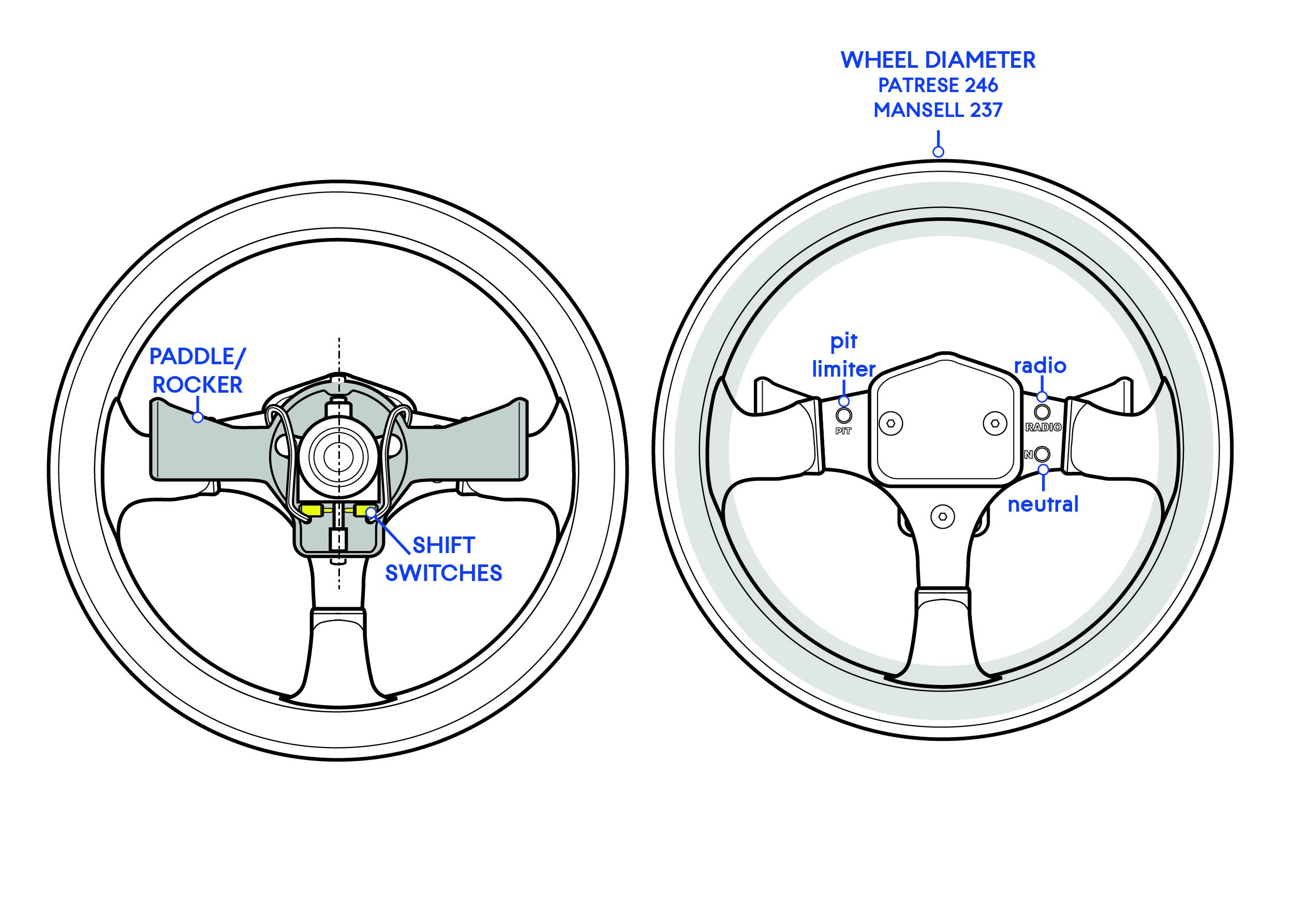
To work the system, a hydraulic feed was taken from the pump/reservoir above the gearbox and solenoid valves directed the fluid to the gear selection ratchet. Control was from the steering wheel where a rocker mounted the two sift paddles, and mounted to the rocker were the two switches that initiated the shift. A benefit of the rocker design, was that the driver could push or pull each paddle to gain an upshift or downshift, depending which hand’s fingertip was best disposed to use the paddle.
The gearbox itself was Patrick Head’s work, an engineer happier with the mechanical rather than aero side of design. This was a transverse unit, this kept the length short, to aid the rearward weight bias and wheelbase short. At this time there wasn’t the aero demand for an ever longer wheelbase to shape the sidepods. Even with the rearward splayed radiators the coke bottle shape was acceptable for the era.
Renault V10
After the turbo era, Renault stepped forwards with a different take on the normally aspirated 3.5l engines, the V10. This was an unusual option for a race engine at the time because most engines were a 12 or 8 cylinder and each had its pros and cons. The V12 is a perennial favourite of the racing fans, albeit its success in F1 was limited largely due to its drawbacks. Yes, the V12 was powerful (and loud), but it was fuel hungry, very long and thus very heavy.
Needing to accommodate a long V12 and large fuel tank is the antithesis of ideal for the race car designer. Meanwhile the V8 was the inverse, small and light, but it struggled to make the same power with fewer cylinders. Renault therefore went for the middle option, ten cylinders! The compromise in packaging and power was ideal for the new era.
Renault’s lessons from the turbo era were carried over, the engine ran pneumatic valve return springs (PVRS) discarding the coil valve spring to allow greater revs and less maintenance. Also, with electronic control of fuel injection and ignition was achieved with a dedicated ECU supplied by Magnetti Marelli, mounted in the righthand sidepod.
Even in its third generation the RS3 as was installed in the FW14B was an engine combining a mix of cutting edge and quaint technology. Despite the High-Tech ECU, the throttle was operated by a mechanical cable run from the pedal in the pedal!
When the driver pressed the throttle pedal there was another modern system to help them, every bit as modern as the active ride, traction control. As the car now ran wheel speed sensors and a powerful ECU, a map could be set up to rear the front to rear wheel speed differential. If the rear wheels are going faster than the fronts, then they must be slipping from a lack of traction. The ECU accordingly retarded the engine until the speeds equalised, providing the driver with maximum traction out of the corners.
Keeping the RS3 cool were oil and water, the oil cooler was a water jacketed set up mounted to the left of the engine. This used the engines main water-cooling circuit to cool the oil, meaning no oil cooler was mounted in the airstream. Instead, the sidepods housed just two large water radiators each plumbed directed into the cylinder head and cooled water returned via pipes to the rear of the engine.
A large water header tank was fitted into the system and mounted in the right hand sidepod. Additional cooling was provided with a small hydraulic oil cooler in the lefthand sidepod and the gearbox oil cooler mounted between the rear wing mounting plates.
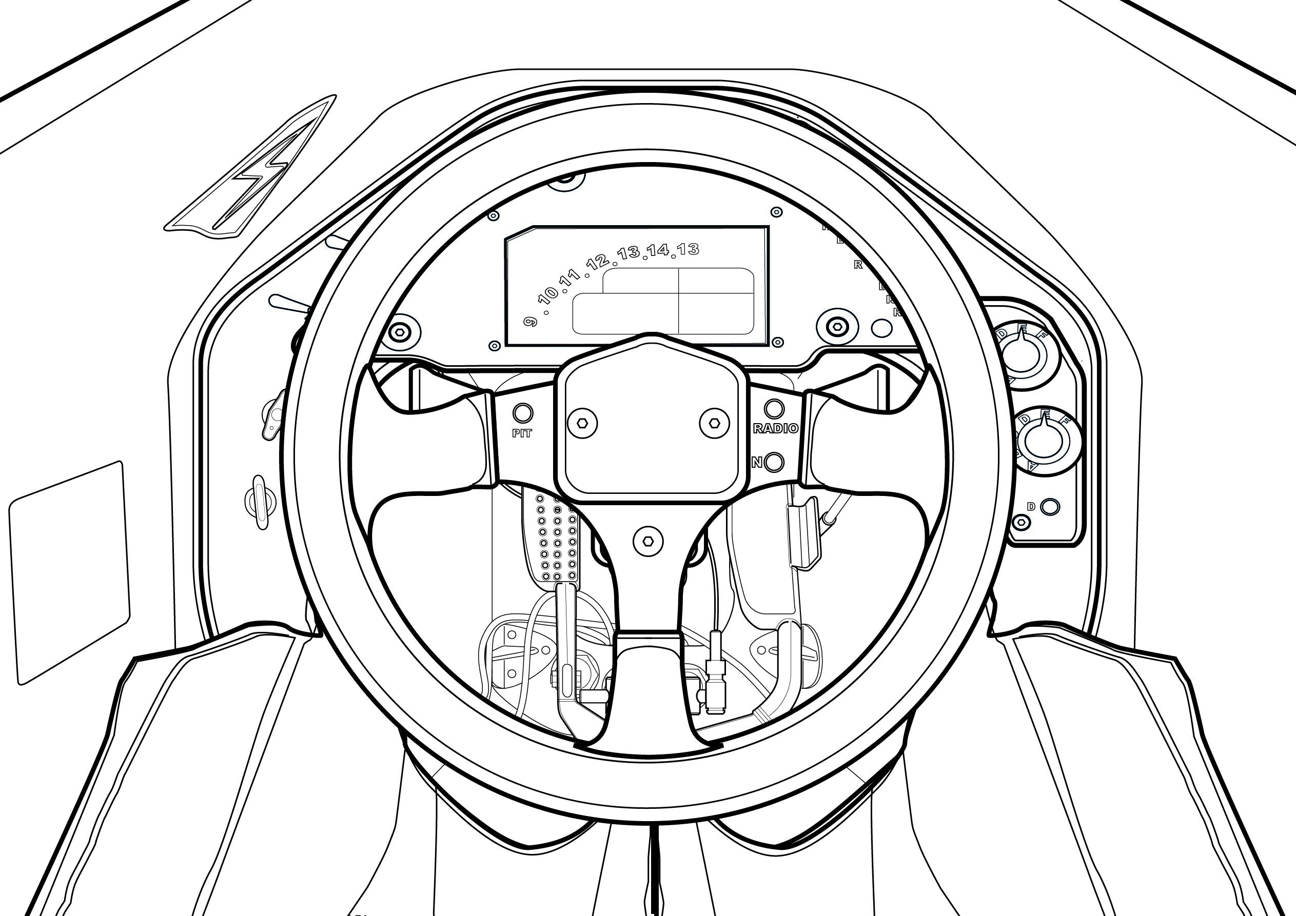
Cockpit and operation
Sitting inside the small opening the driver had quite a welcoming cockpit. While not spacious, the broad-shouldered Mansell was able sit in a fully upholstered seat that spanned the width of the cockpit. One oddity with the Williams seats of the times is that to fit the entire moulding into the cockpit through the small opening, the seat had to be split left and right and fitted one half at a time!
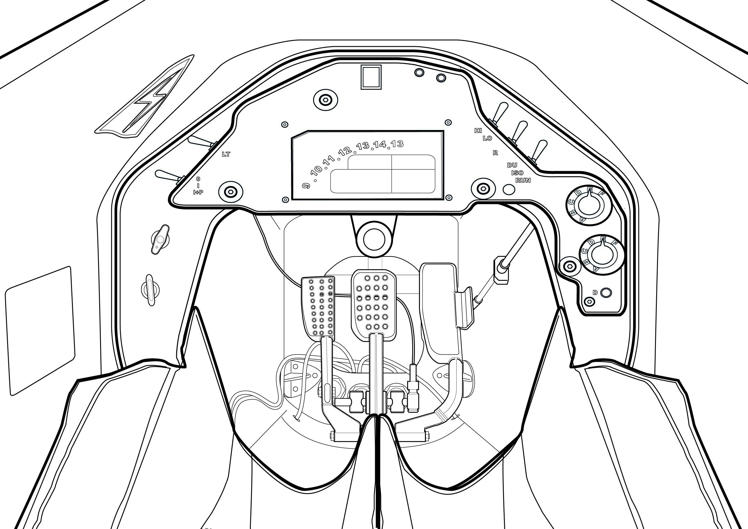
Ahead of the driver was the steering wheel. Patrese ran a small 246mm diameter wheel, while Mansell wrestled with just a 237mm diameter wheel. This was still a conventional round wheel and behind the wheel was the gearshift rocker/paddle and three buttons were allocated to control the chassis/engine functions. By now the generally smaller cockpit spaces had enforced all teams to run a removeable steering wheel, the end of the steering column having an electrical connector built in to join the steering wheel buttons to the main loom.
Behind the wheel the car ran a dashboard, lights at the top of the dash provided a shift LED, puncture warning light and active ride warning light. Then there was a digital LCD display for RPM and engine parameters. Around it there were several buttons to control the car’s basic systems (Ignition, Rear Light, radio etc). As well as the buttons, there was the novelty of rotary switches, which controlled the engine maps, traction control settings and active ride settings.
Nowadays the driver have an array of systems they could adapt on the move to get the best out of the car, which started the movement towards the complex steering wheels and control systems that the modern F1 driver now has access to.
But it was the Williams FW14B that was arguably the true tech ground breaker that paved the way not only for innovations in the automotive industry but also changed the face of Formula One.
Motorsport Technology is an Acronis initiative and Acronis are proud to be the official Cyber Protection Partner of Williams Racing. To find out more, please visit https://www.acronis.com/en-us/lp/msp-sports/