In the spectacular setting of the Styrian mountains, the European summer heatwave affected more than just the fans watching the Austrian Grand Prix, the F1 cars are having to cope with the heat as well. With air temperatures in the mid 30c and track temperatures of 45c, as the cars are driven hard around this power-hungry track. As a result, all systems on the car are being pushed towards their maximum temperatures.
With 1000hp on tap from the combustion engine and hybrid systems combined, an F1 car puts out an incredible amount of heat. Keeping this and its attendant systems cool is a major task for the team, both at the design stage and when at the track. Cooling aids reliability but costs in performance, with added weight and aerodynamic drag.
What gets hot and needs cooling?
From nose to tail, any powered device on the car requires some cooling. Although we consider the engine as the major element that needs to be kept cool, there’s also the hybrid system, hydraulics, gearbox, clutch, suspension and electronics. You could add the driver and brakes to the list, but we will leave those aside for the purposes of this article.
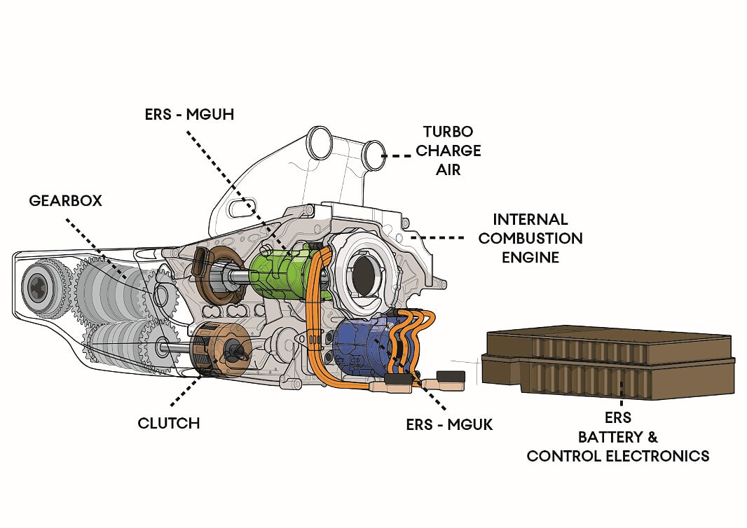
The primary contributor to the cars cooling system is the Internal Combustion Engine (ICE) with its turbo and hybrid system. Back in the V8 era, cooling was quite a simple system – water and oil for the ICE, along with a small cooler for the KERS set up. With the switch in 2014 to the new specification power units, the ICE heat rejection was actually lowered, so less cooling was required. Although this decrease was offset by the greater cooling demand for the hybrid system and turbo. Some 30kw less heat was put out into the water cooling circuit, down to 90kw, and equally the oil heat output was down to 30kw.
Whilst we use the term water, the actual fluid is a water/glycol mix. This is kept under pressure at over 2.5bar to raise the boiling point, so that the engine can be run hotter at +120c in order to reduce the size of radiators required.
Oil, likewise, is kept under pressure, although it’s more the circulatory effect around the engine than for cooling. Thus, the oil runs at +100c and at 1bar pressure. For some teams, it appears that the oil for the turbo is run in a separate circuit to the engine oil, so it can run at different temperatures and pressures.
Equally, the increased sophistication of the post 2014 power units brought complication to the cooling system with thermal management of the Hydrid system’s; Battery, MGU’s and Control Electronics. These run at much lower temperatures than the ICE, their cooling is achieved by either water-based coolant or dielectric fluid (oil). Running at around +50c they greatly affected by the ambient temperature going above 30c.
F1 cars have always run gearbox oil coolers, typically mounted at the back of the car. Gearbox temperatures are critical for reliability, but far less of a tax on the designers, with a heat rejection figure of around 10kw. Since the mid-nineties, there has also been the demand to cool the small volume of Hydraulic fluid used for the car’s control systems down to around 100c.
Away from the power unit, the cooling demand is far less, but still as important. Most other systems are cooled by air. When you consider the tight confines of an F1 car, then the designer’s task to pick up some airflow and direct it deep inside the car is particularly tough.
In a similar position on the car the rear dampers and other hydraulic suspension hardware needed to have temperatures contained, although the front mounted suspension hardware is less of task to cool.
Lastly, all of the electronic hardware is also sensitive to temperature, major components like the ECU and powerboxes have the greatest cooling need. But hardware, such as the laser speed sensor pointed downwards under the nose, requires significant airflow to pass over its cooling heatsink fins to keep cool. Every electric box and sensor needs some airflow to contain temperatures, teams even feed air to the brake temperature sensors with clear tubing picking up air from the brake duct.
What happens when things get too hot?
With regards the powertrain, thermal management is a primary means to achieve reliability. When temperatures rise even by a quite small amount, power from the engine will be reduced from the hotter air temperatures, but more critically the reliability suffers.
Materials are pushed closer to their structural limits and aluminium weakens at raised temperatures, affecting the crankcases and gearbox castings. Heat also leads to thermal expansion of the metals; this closes the design tolerances, so parts can seize or loosen depending on the surrounding materials. Oil loses its lubrication effect, with film strength dropping at raised temperatures, again leading to seizing. With electronics, the semi-conductors fail with increased temperature, stopping them from working.
Clearly, not coping with the expected cooling demands is a sure fire way not to finish a race or finish compromised by a loss in performance or failed sub-system.
How are things cooled?
Liquid cooling is easily the main way to cool the powertrain, with the water or oil.
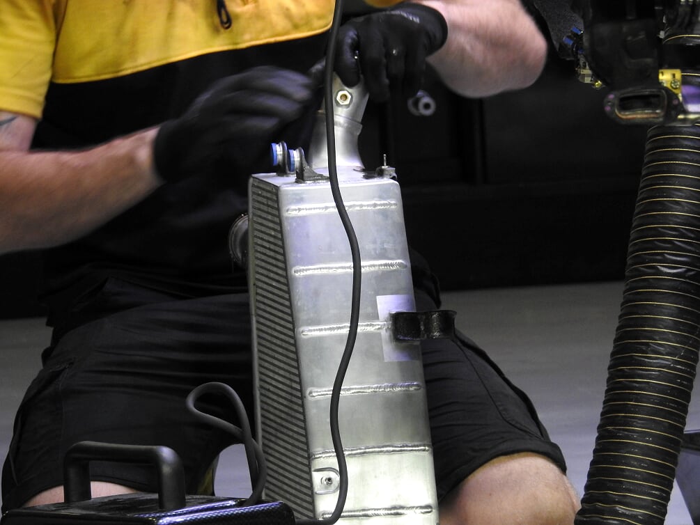
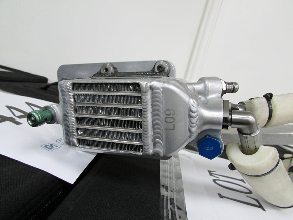
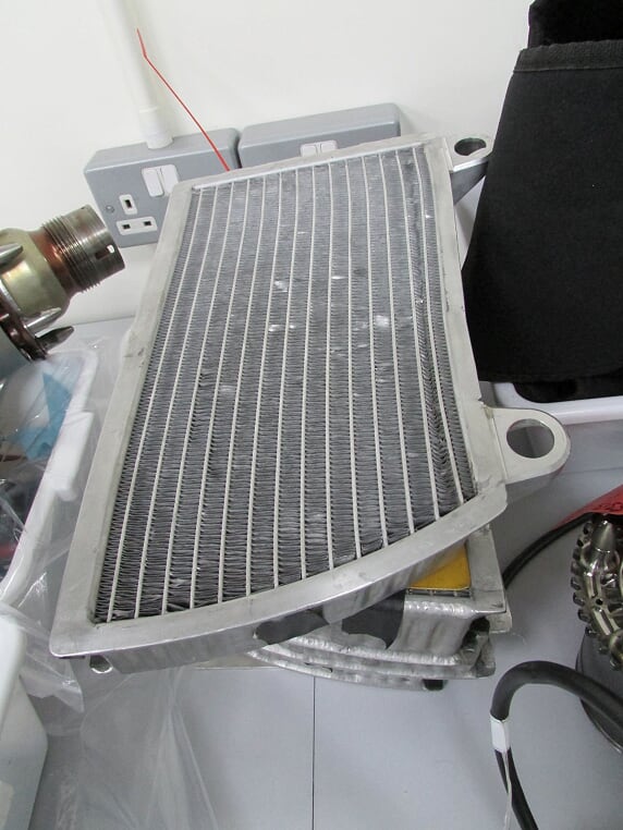
Liquid cooling infers a heat exchanger is used. So, the water or oil will pass through the tubes within the heat exchanger and the heat is passed through the surrounding fins to the air passing over the unit. For water heat exchangers, we tend to the use the term ‘radiator’, although oil cooler and charge air coolers (intercoolers) are similar terms for similar hardware, but with a different fluid being cooled.
By surface area, the ICE water cooling is by far the largest demand on the cooling system. Coolant is circulated around the engine and radiators by an impeller type pump driven off the crankshaft. Oil, conversely, is circulated by a gear type pump, although it is also driven off the engine.
Cooling the charge air, heated up by being compressed in the turbo, is achieved with a charge air cooler (CAC). In F1, there is a split in how teams achieve this. The typical method is with a CAC cooled by airflow, which is called an air-to-air intercooler. This is a light/simple setup and the cooling effect is good. However, the large surface area required for the CAC to meet its temperature drop means that the cooler is quite large and must be fed with a large amount of cooling air. This can compromise aerodynamics, due to the space taken up within the sidepod by the set up.
Another means adopted by Ferrari and Mercedes since 2014 (plus Lotus\Renault for 2014 only), is where a water jacket cools the charge air inside the heat exchanger, rather than air flowing through it. Termed a Water-to-Air intercooler, this set up requires a separate water-cooling circuit, complete with its own pump and water radiator.
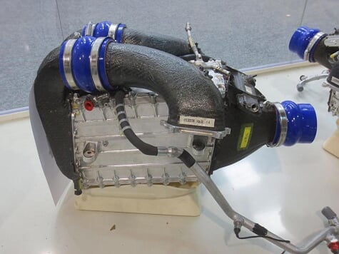
With this set up, the intercooler is smaller in volume and no longer needs to sit in the airflow, although the secondary water radiator does need to be fed with cooling air, albeit this radiator is far smaller than an intercooler. This opens up a packaging advantage for the team, with Ferrari and Mercedes now placing the intercooler well out of the way, in front of the engine. In terms of cooling and weight, the water-to-air set up is less efficient, it’s heavier, and the charge air temperature is higher. But the temperature is more consistent, especially when the car is running slower, such as when it’s sat on the grid, because the primary cooling is the water and not the passing airflow.
Much of the added complexity to the cooling arrangement on the current cars comes from the ERS, with the Battery, MGUK, MGUH and Control Electronics each requiring cooling. There are dedicated cooling systems for the ERS, so they do not use the ICE cooling systems. This may require two to three cooling circuits to suit the different cooling fluids and locations of the hardware. Now that the Battery and two Control Electronics packages are placed together under the fuel cell by regulation, they are likely to share the same cooling system. Dielectric fluid is circulated by a dedicated electric pump with a small cooler mounted in the airflow. This leaves the MGUs separately cooled by one or two circuits with a water coolant and radiator. As the MGUs are mounted to the front of the engine, there can either be a mechanical impeller pump driven off the engine or an electric pump.
Both the gearbox and hydraulic systems use their own pressure pumps to flow the oil to small oil coolers.
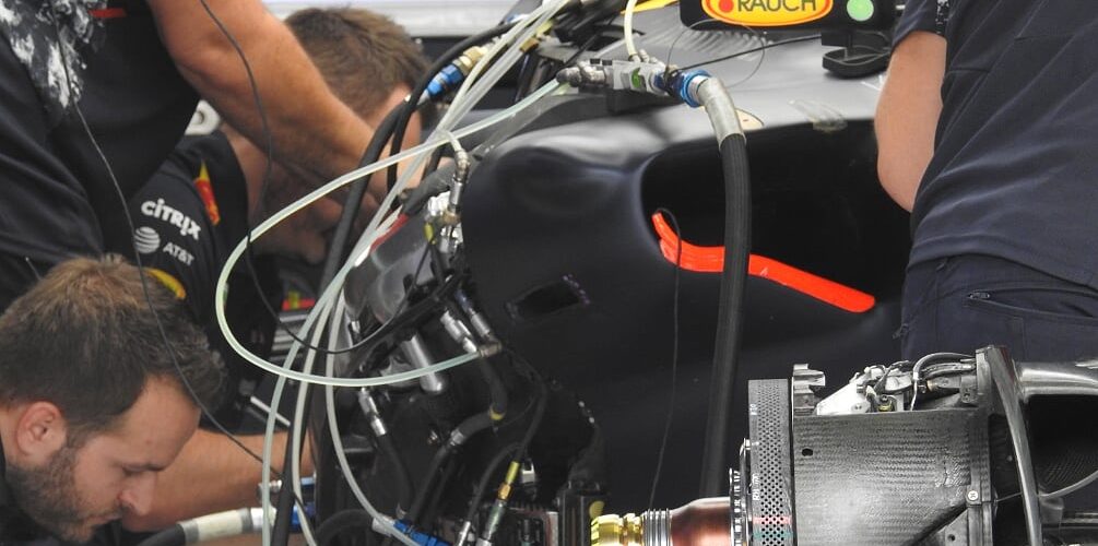
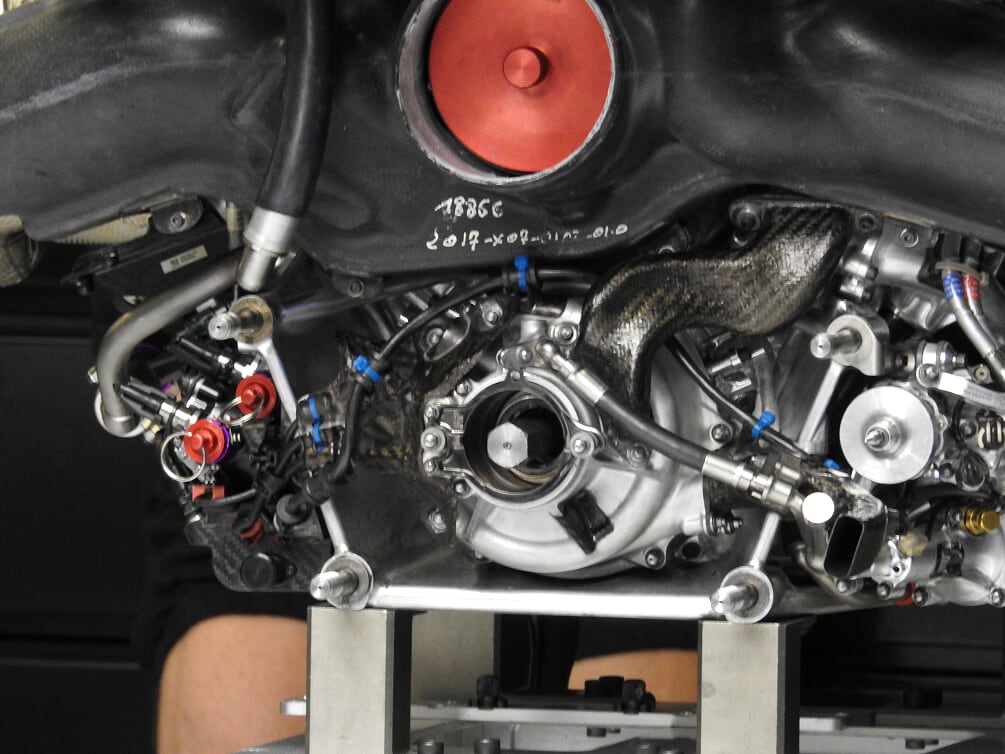
Connecting all of these systems to their heat exchangers and pumps requires plumbing, and a lot of it! It is this that creates the visual complexity to the current cars, made worse when the car is being assembled and the various pre-heater and bleed pipes are temporarily attached, a bit like a life-support network around the car.
Pipework is carefully designed when the car is first realised in the CAD system. Nothing is left to chance and fettled through final assembly. As important as the pipework, the designers need to account for a means to pre-heat, flush and bleed the system when installed on the car, incorporating many extra dry break connectors into the cooling circuit’s pipework.
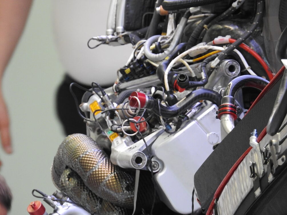
The pipework itself is a mix of mainly rigid piping and some flexible pipework depending on the system and location. Larger bore rigid pipework can be formed in aluminium or moulded in carbon fibre (for the higher budget teams), while smaller bore pipes tend to be fabricated in aluminium or titanium. Connecting all the pipe-ends together to form a sealed system are dedicated motorsport connectors. These are more effective and reliable than silicone hose and jubilee clips, with suppliers such as Wiggins, Teconnex and Staubli used.
Radiator layout
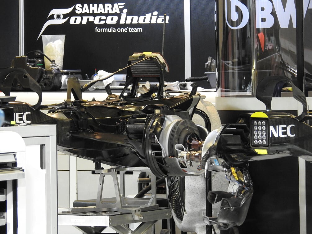
Once the cooling demand is specified and the associated radiator core area is defined, then it’s a cycle of work between the design team and aerodynamicists to decide on the overall cooling aero concept and the amount of space in which to fit the coolers. After which, it goes back to the design team to detail the actual installation.
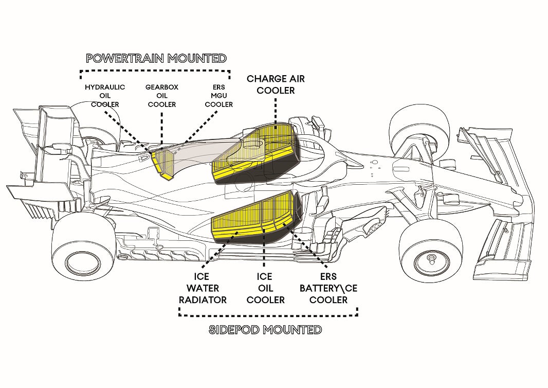
There are two places you can mount coolers, either within the sidepods or in the area above the power train fed by the roll hoop inlet. Each have their attendant benefits; sidepod coolers are easy to mount, they are lighter, and their weight is lower in the car for a good Centre of Gravity (CoG) height. But wide sidepods affect airflow the rear of the car, which is bad for performance.
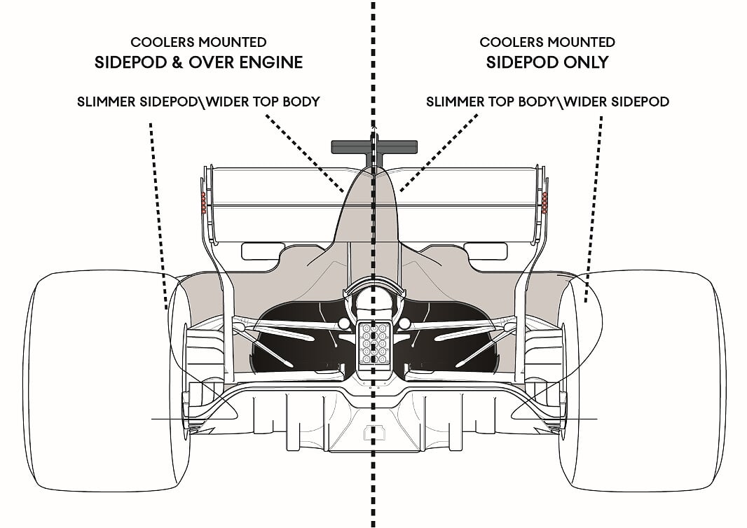
In contrast, mounting some coolers up over the engine is just as good as it takes the volume out of the sidepods. This benefit is partly offset by a larger obstruction of the top bodywork to airflow to the rear wing. Also, the overall weight may be higher in order to run cooling pipework up to the ideal position and their weight is placed higher in the car raising the CofG height.
The engineers all make their compromises, and neither is a superior solution. McLaren, in recent times, have tried as little as possible in the sidepods to create the size-zero MP4-30, while last year’s car had everything in the sidepods on the MCL33.
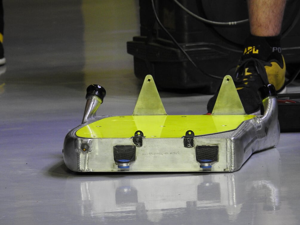
The detailed work then decides how the radiator core is positioned relative to airflow and how the pipework routes to the coolers. Of course, the sculpted shape of the sidepods makes it hard to package large rectangular coolers, so the designers must be inventive with the shape of the radiator and the ductwork around it.
Whilst the heat exchanger passes its heat into the surrounding airflow, there will always be a delta between the cooler and the airflow, which means that the airflow may still be able to cool something else after it passes through the cooler.
As different coolers work at different temperatures, they can be stacked to use the same airflow twice. With lower temperature coolers having high working temperature ones mounted behind them. This is a neat way to package lots of coolers into a smaller space.
The same trick can be employed within a single cooler, rather than flow going in one side of the core and out of the other, the core can be doubled over. This trick is often used to package more core area into the cooling package and, usefully, the inlet and outlet pipes are all on one side for easier packaging.
Cooling aero

To make the heat exchangers work, air needs to pass over the core of the radiator. With the speed of the cars, the airflow is way too fast to be effective at drawing heat from the coolers, so the ductwork inside the car serves to slow the air down as it meets the radiator and then speed it up to exit the bodywork. Thus, the duct is formed of an inlet, an expanding cross section, space for the radiator\s and a converging shape to an outlet larger in cross section to the inlet.
Getting airflow into the radiator duct is a simpler task than getting it out. There is a powerful airflow approaching the sidepods (strongest right next the vertical side of the monocoque), but the aerodynamics also like to use this for downforce rather than cooling, so the shape is compromised between the two needs.
Tailoring the cooling effect of the bodywork is not dictated by the inlet, rather it’s the outlet that is adapted for different conditions. So, the inlet doesn’t tend to be altered in shape or size for each circuit.
Before 2009, sidepod outlet design was free. Teams could make holes in the sidepods of any shape they wanted; outlets, cooling chimneys and louvers were all employed to vent the heated air from within the bodywork. In 2009, the rules enforced a closed sidepod design, with only a few areas excluded to allow cooling openings. This is why we see teams all exploiting the same spaces for their cooling outlets.
Thus, the sidepod is split into three volumes and the cooling outlets are only allowed in; the front top of the sidepod at the cockpit side, along the centre of the shark fin, the tail exit of the sidepod and out of the lower 50mm of the sidepod.
Each has a resulting effect on cooling and drag. It’s a problem for the teams that any opening of the bodywork to aid cooling brings with it drag, and to a lesser extent, downforce trade-off. This is where the race engineering conundrum comes into cooling. Teams want performance but also reliability, so cooling must be traded to meet the team’s goals. There is nothing for free with this trade off.
Teams will utilise lap time simulations to work out a specific track’s demand on cooling and its sensitivity to cooling drag. It may not seem obvious, but some tracks place greater demand on ICE compared to ERS cooling, as we saw in Austria, so the cooling set up needs to vary to account for this.
As well as factoring in the ambient temperature and the data collected from the car, the race engineers will have to trade temperature for performance over the weekend by tuning the bodywork to increase\decrease the cooling outlet area. To aid this, more simulations have predicted the effect of any combination of the removable cooling panels they have on hand. This is literally an electronic catalogue of cooling effect versus drag, with CAD images showing the bodywork set up to achieve each specific target. It will be employed to get the ideal set up for the track conditions.
Teams will have several different bodywork options to fit into the available cooling outlets. Starting with the coke bottle exit (this is the tail of the sidepod) its width and resulting opening to the rear is the main means to tune from high to low cooling requirements. Seeing the high cooling to low cooling options, it’s clear to see how aerodynamics are affected by the need for a lot of cooling, with much larger sidepods fitted to the car.
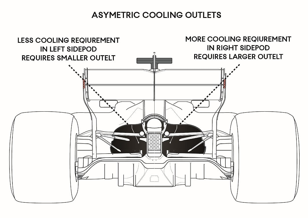
As the radiator package within the car is not symmetrical (often with the ICE radiators in one sidepod and the ERS\intercoolers in another), the heat cooling requirement is different from left to right. To meet the specific cooling needs of each sidepod, the outlets can be different sizes, so the rear view of the sidepod can often be asymmetric to get the ideal balance. This is not some clever practice for increasing performance at tracks, that have more corners in one direction than the other, as is sometime thought.
From here, the finer tuning of the cooling set up is largely done with the cockpit side outlets. These small panels can be completely closed, for a low drag set up. Increasing numbers of louvered opening and even a rear facing outlet can also be formed into the legal area.
This region can also be used to tune the cooling in the race, if the temperatures are expected to change, or simply the second stint of the race is run faster due to the diminishing fuel load. These panels can be altered during the race because parc ferme rules dictate that whatever bodywork set up you finish qualifying with, you must run in the race. So, you cannot start the race with different cooling outlets and there is no time at pitstops to unbolt and replace the outlet for different sized one. Teams such as Mercedes get over this by covering the louvered outlets in qualifying with a thin carbon cover. This is merely taped on, strong enough not to be blown off at speed, but easy enough to be ripped off by a mechanic at the pitstop if more cooling is required.
It’s less common for teams to currently use the front top sidepod outlets, which come in and out of fashion. Also, the space along the car’s centreline either side of the shark fin is a case of trends. Currently, only Mercedes tactically employ an outlet here, with the chimney like outlet on the top of the engine cover used at particularly hot races.
Otherwise, the detail of the cooling set up is to cope with specific hot spots, and some teams will run louvered openings low down in the coke bottle area to cool the exhaust at specific tracks.